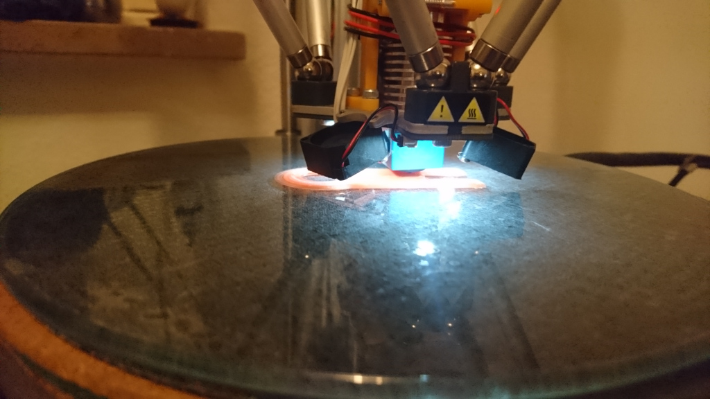
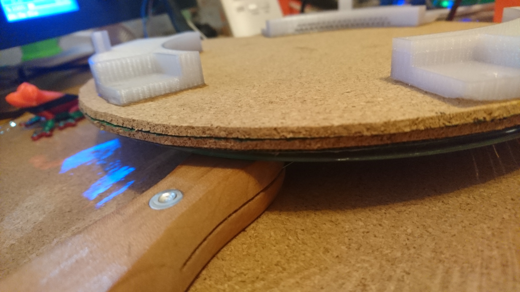
Cork works fine for thermal insulation. I see no difference in the piezo sensitivity. As you can hear in the video the knocking sound when the nozzle probes the glass scared me a little in the beginning, but I think both glass and nozzle survive it undamaged.
Yesterday I printed in PETG with blue tape to protect the glass. No knocking sound audible while probing.
Great work, maybe you could improve the first layer with babystepping in marlin (preferably 1.1.9 since it’s broken in 1.1.4). I have had to put my heated bed on hold sadly because recently after swapping the bent heatbreak I cannot print for more than an hour without jams.
What do you mean with broken in 1.1.4? I have activated it (not with double click but via tune menu) and for me it works fine.
Your heatbreak is bent? I’m sorry to hear that. I hope you can fix it.
I found that combining the babystepping with z offset made the printer act weird in my case. On 1.1.9 similar config works fine.
My heatbreak was actually broken and I swapped it for a cheap replacement, now the hotend keeps jamming after a while, I’ll try PTFE heatbreaks but I’m already planning to order a genuine E3D lite6 hotend which didn’t give me any troubles in my previous printer for like 2 years or so.
@riodoro1 thank for the explanation I never tried z-offset so I had no problem with baby stepping so far. A small thing which helps I think is #define PROBE_DOUBLE_TOUCH two measurements are always better then one.
I’m not so a big fan of this collet and collet clip thing of E3D. I like the screwed pneumatic connectors of the stock K8800 more.
Yup im not a fan either. I mean it worked great until it broke and I could not get it anywhere. I just threaded the collet to M6 and fitted a PTFE connector there. The thread was very short, like 1mm maybe but the connectors only get hand tightened anyway.
About that babystepping, I tested further noticing it does not work in 1.1.9 and in 1.1.4 when it’s combined with z-offset, on 1.1.4 when BABYSTEP_ZPROBE_OFFSET is not defined babystepping works fine.
It’s very strange since I found that Marlin 1.1.9 executes the code where it sends a step pulse to each motor but somehow nothing happens, in 1.1.4 (without z-offset integration) the printer enters the same method and in fact does step the motor. In 1.1.4 with z-offset integration this code does not get run so there’s some different logic that prevents it I think.
I fixed the babystepping in 1.1.9 by increasing the minimum stepper pulse width in Configuration_adv to 3μs. I think the pulse delay calculation might be off tho. Pushed the updated 1.1.9 to my github repo.
I found that the pulse width was a problem because it worked with serial debug commands in between writing low/high to the step pins.
The DRV chips should require 2μs pulses (that’s the default in marlin) and thus I increased the value by one to check if it would work, and it does.
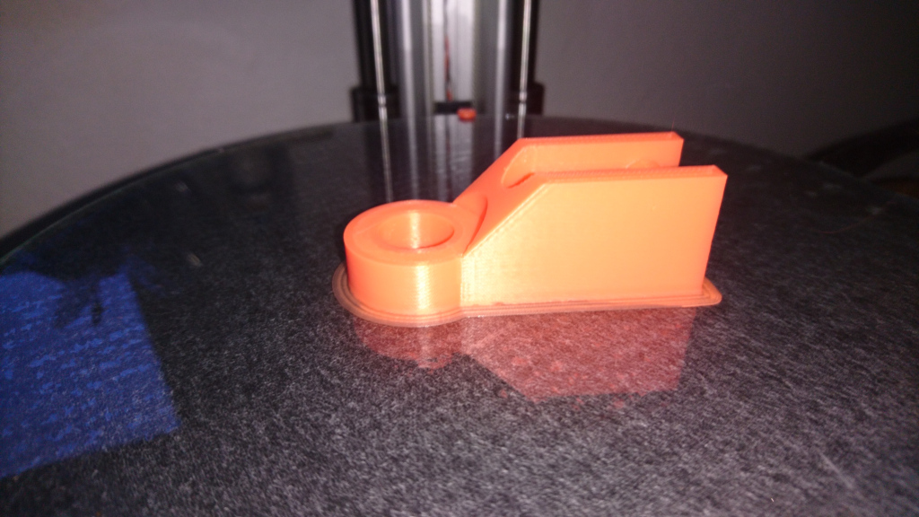
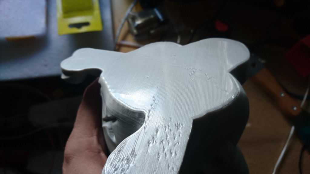
It’s all quite strange to me really because originally the _PULSE_WAIT macro in stepper.cpp:2236 evaluates to DELAY_NS(2*625) and combined with the fact that X,Y,Z step pins are written sequentially, not at once, means that each one should be low for at least 4*625ns or 2.5μs. Maybe that is not enough for the chips used on my printer, maybe that’s the board layout fault or maybe the delay is off. I would have to measure the actual pulse width with an oscilloscope to be sure and maybe I will do just that tommorow since I’m planning to take the PCB out by then in preparation for my own heated bed. All I know is that with 3μs minimum pulse width the babystepping works and that makes me quite happy on large footprint parts
Since we’re back on the topic of heated beds, what thermistor did you use on yours? A typical NTC? If so did You have to add a resistor to pull the input HIGH? I’m still quite torn between a separate W1209 based controller or a mosfet being switched by Marlin and after favoring the separate approach that would not require any modifications to the printer I’m slowly leaning towards the Marlin approach since Velleman left that nice 9x2 pin header on the board… I would like my bed to be removable because I love how well PLA prints on the original buildtak. I’m thinking a small 4 pin DIN connector on the side of the printer…
Yes.
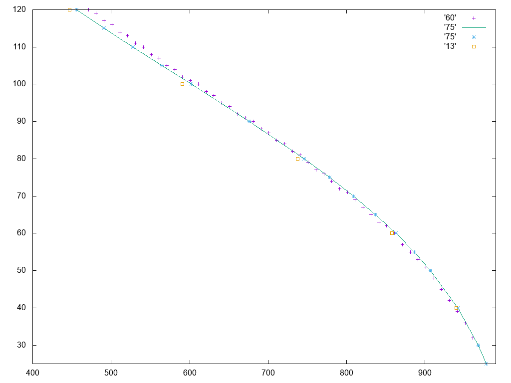
The silicon heat pad I use has the thermistor build in a typical beta3950. I checked by comparing thermistortables**.h with Gnuplot that #define TEMP_SENSOR_BED 75 //100k Generic Silicon Heat Pad with NTC 100K MGB18-104F39050L32 thermistor
works best for that purpose.
I’m using a small pcb for the pullup and the connection to the mosfet with a JST-XH4 connector to the printer (reusing an old stepper cable) and pins (dupont) for the thermistor.
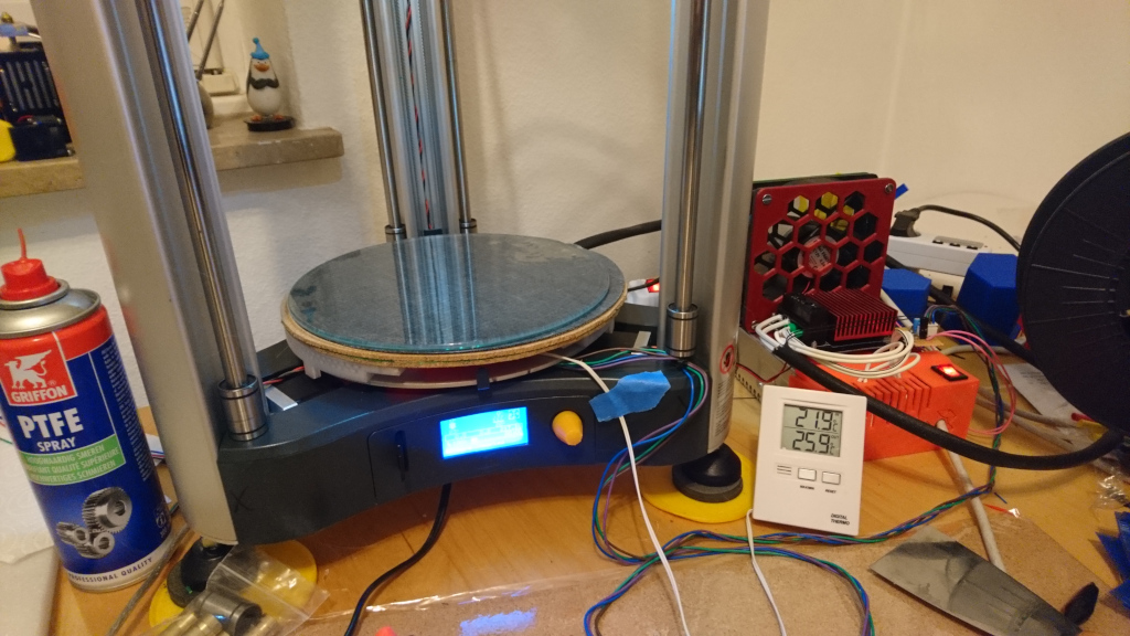
I checked already with my printer. It is still possible to print without heatbed on Bulitak or PC-foil. (I had just to increase delta height to suitable value, in my case
Do You really have to change the delta height in firmware? I run tests on mine where all I had to do was run height calibration forn the menu after installing the heated bed and it worked well enough.
Do you use any MOSFET boards or just the transistor by itself?
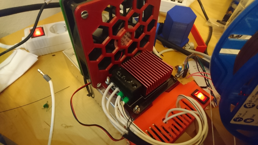
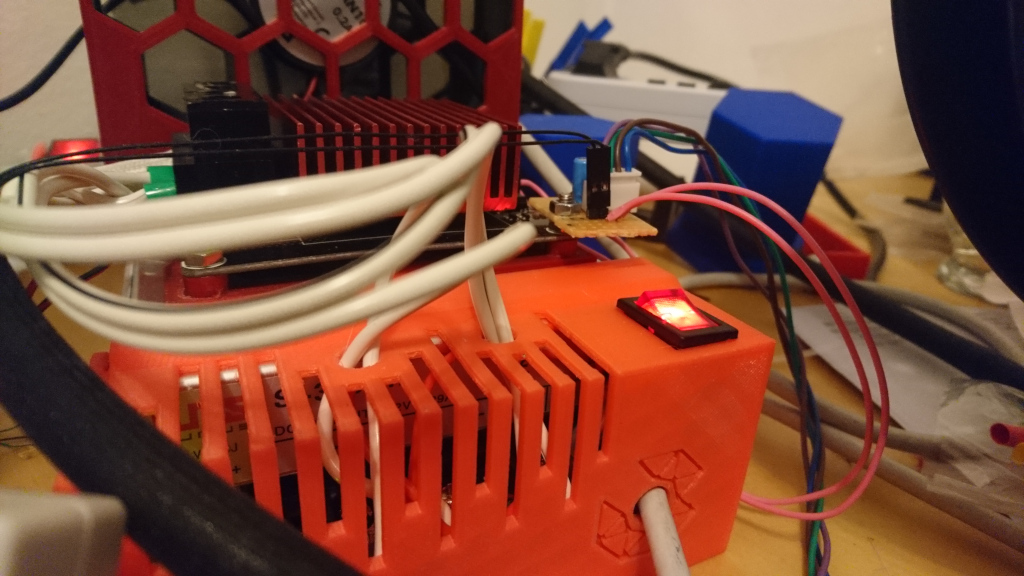
I can always stay with the greater value. If it is to low then I can Calibrate height or Calibrate but when printing or calibrate X/Y/Z/Center it will never reach the bed. I’m using a MOSFET on the first picture in this thread you can see it (red heat sink)
I think I’ll just use an IRL7833 and thermally bond it to the heatbed
That way everything will be on one PCB on the underside of the heater. We’ll see how it goes.
Ok, so the weekend is here and finally I’m getting closer to having my own heated bed upgrade .
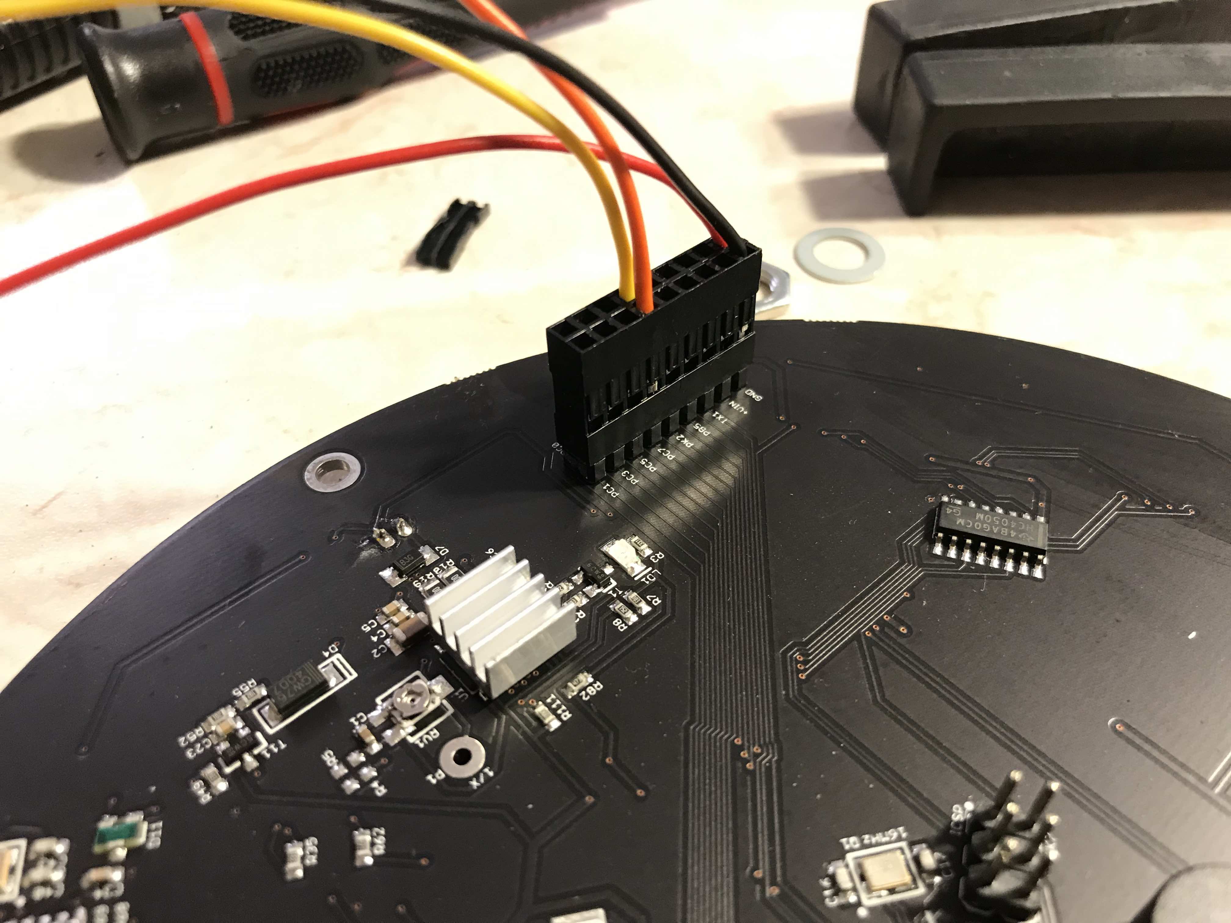
All of the electronics are sorted, first of all I changed my Marlin config, slightly different pins than @shelxle used, I connected my MOSFET to PK6 so it’s next to the thermistor pin and I used a 10k NTC thermistor because that’s what I have already bonded to my bed with previous version controlled by W1209 thermostat module.
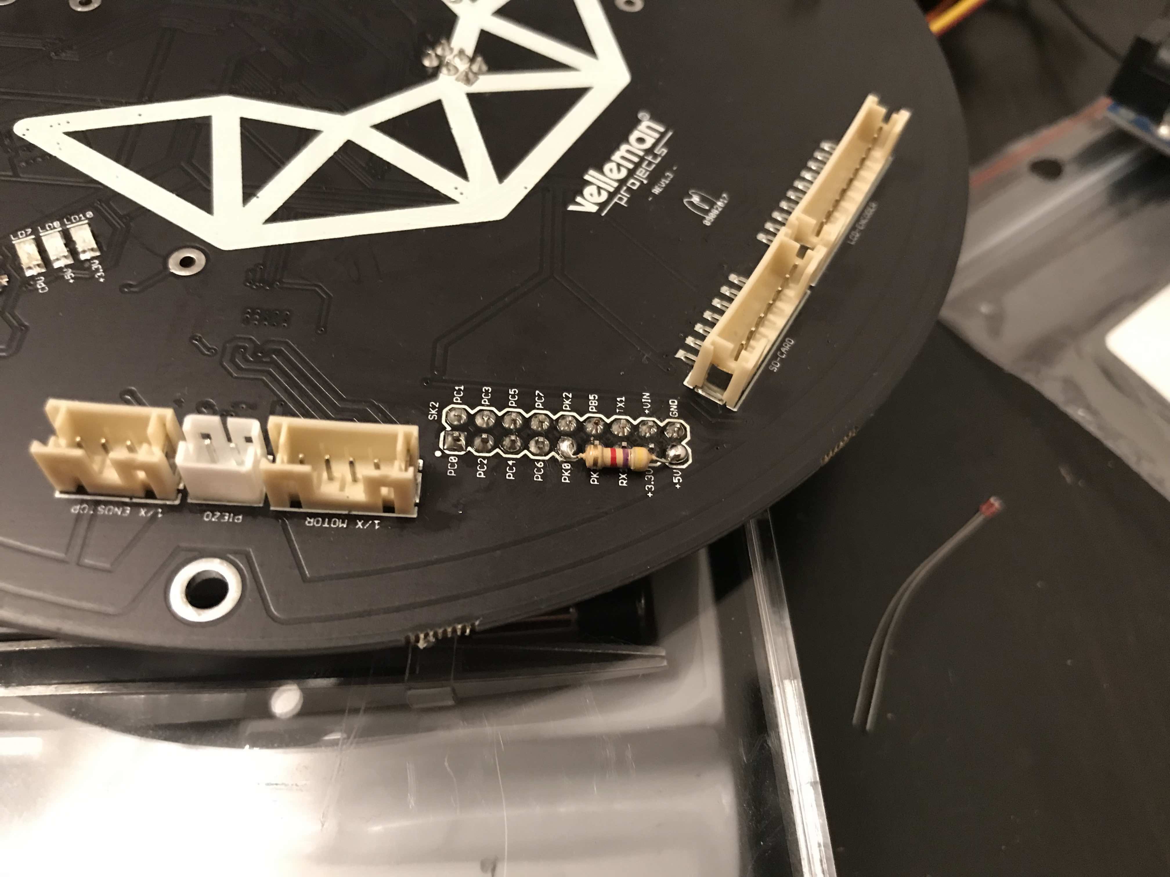
I used a 2x9 goldpin header and connector to connect the pins with the bed. This is how it looks on the board:
And no job is complete without a bodge resistor, this one is the 4.7k pullup for the NTC. I’ve put it here instead of near the bed because when the thermistor gets disconnected the printer would display noise.
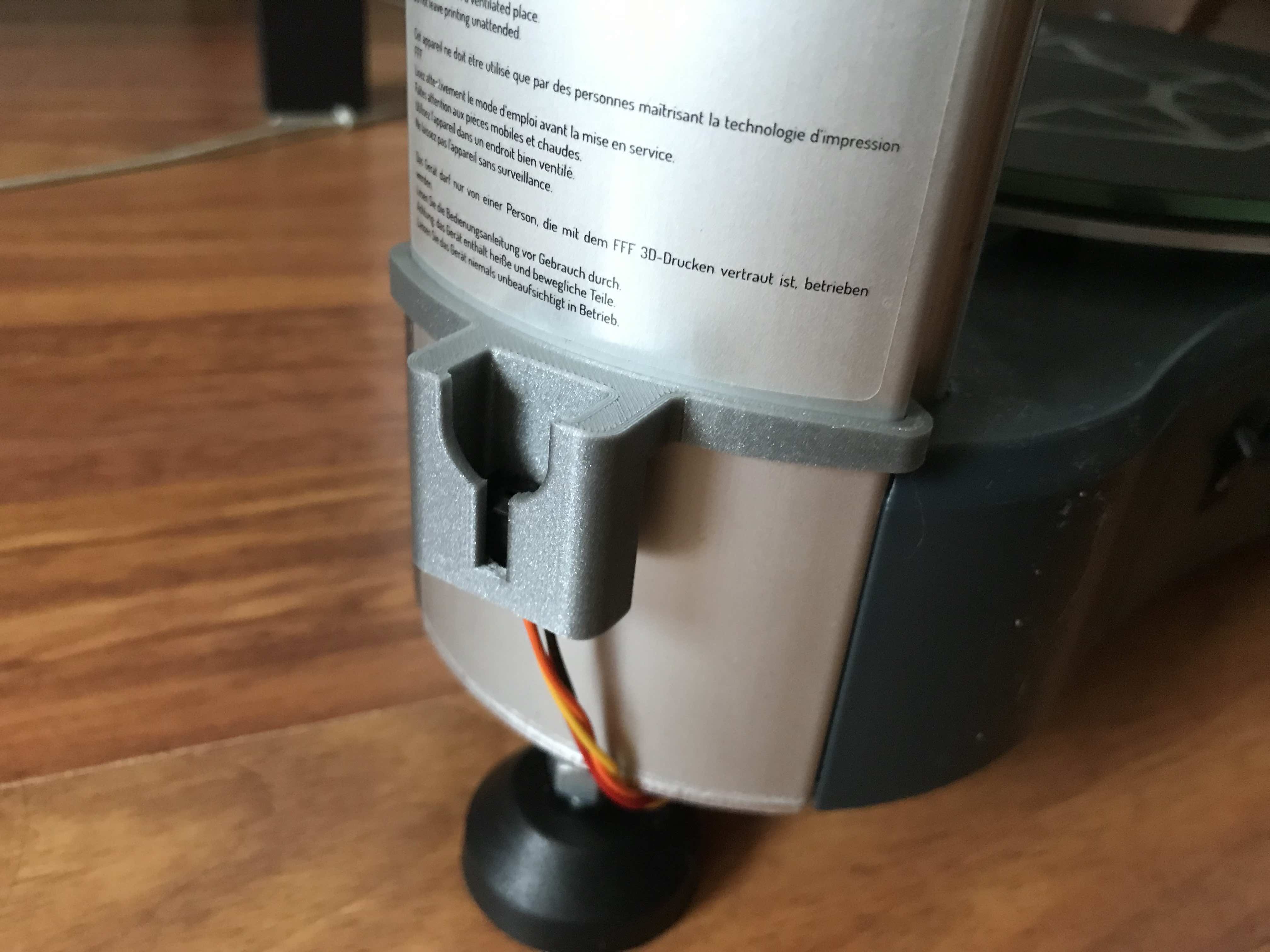
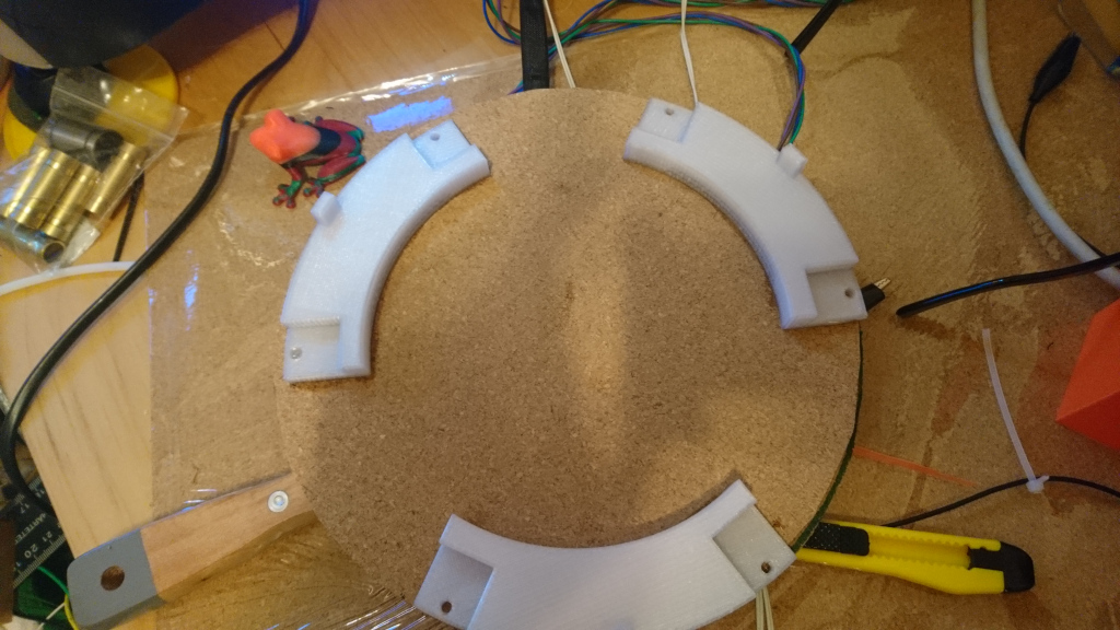
To connect the printer side and the bed side (and be able to remove the heatbed completely when it’s not necessary) I used a 4 pin JST SM connector and printed a bracket for it that attaches to the back tower of the delta.
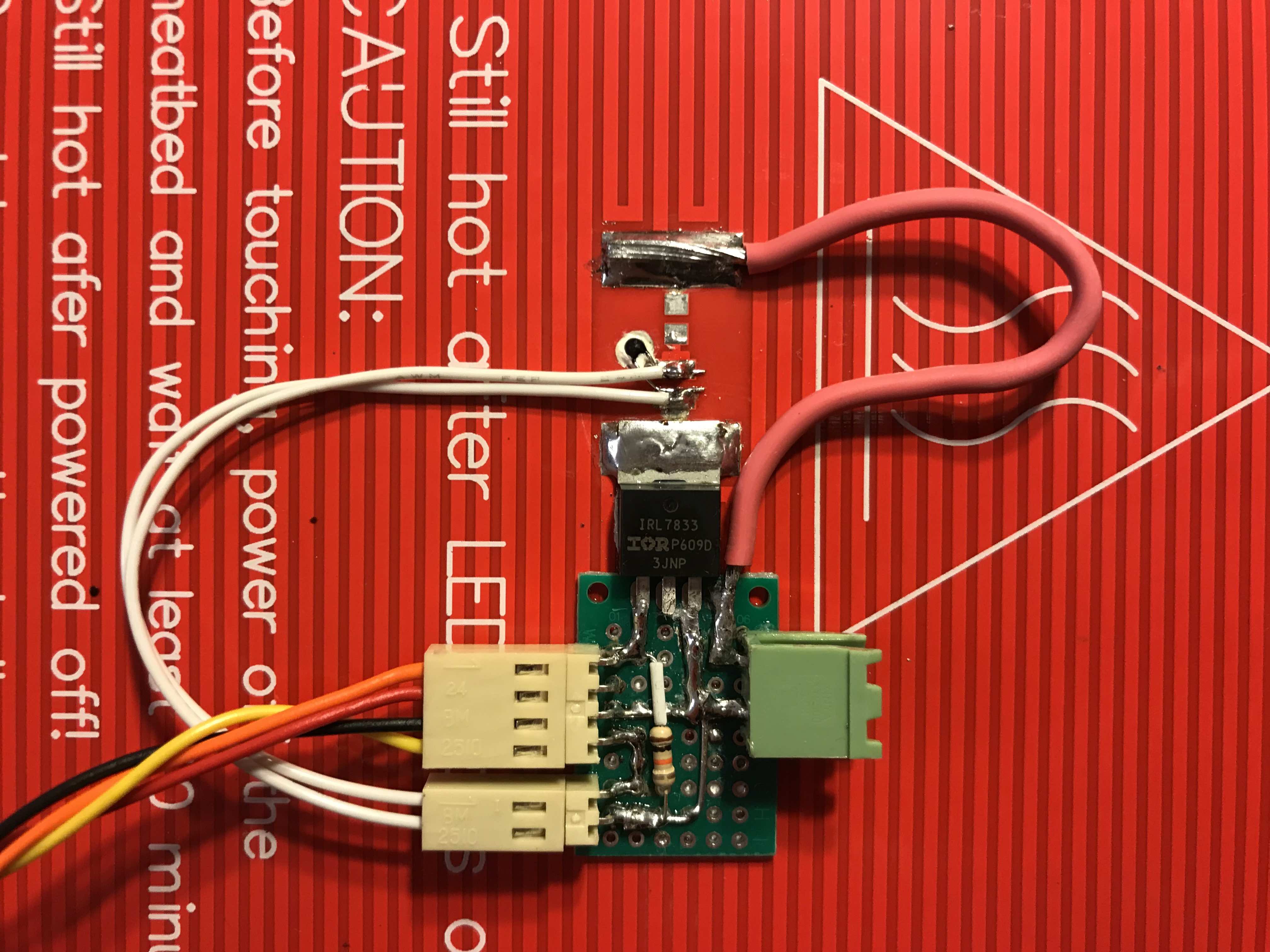
As for the bed I used a typical MK3 aluminum heatbed rated for 12V. Made a little detent in the center for the thermistor and soldered it to the pads originally meant for an indicator LED (after scraping the traces that would connect it across the heater of course). The white stuff around the NTC is thermal adhesive. I wanted all of the electronics to be as compact as possible so I chose to mount the MOSFET (IRL7833) directly to the bed, thermal glue would probably be enough but since the mounting pad of the package is the drain I just soldered it to the pad directly, why I didn’t choose a DPAK version of the transistor you ask? I dunno . The rest of the connections are made on a piece of perf board and it is glued to the bed as well as soldered to the FET which secures it just fine. The green connector is 12V power directly from a separate supply and the 4 pins are what goes to the printer. The resistor here is a 10k pulldown for the gate of the FET. The soldering is pristine I know… It looks much worse in the photo than in real life…
Only thing thats left now is to finish designing and print the risers so the bed can be mounted to the printer. I’m also thinking about adding an option to Marlin so that it doesn’t display the bed temperature at all when the NTC is disconnected (now it shows the lowest possible value which is -34°C in my case).
Have you finished and tested you heated bed yet? please share your results. Do you thermally insulate it on the bottom (pcb side)? How hot does it get on the printers main board? Does that green connector really survive 10A of current?


 )
)