If I’m not mistaken, all of the Velleman 3D printer boards are programmed as “Arduino Mega 2560” boards.
1 Like
Hi all,
sorry I am on parental leave, so there are some more important things to be done than 3d printing ![]()
Are there still questions regarding the heat bed?
The K8800 can be programmed as Mega2560 without issues - just keep my comments about the Arduino IDE version in mind.
Overall my solution works but I am not to happy since the auto bed leveling quite often does not work correctl (nose is ramped into the bed). One reason might be that the spacers are not perfect, expecially when the heat bed is at >60°C they might get to soft so that the bumps are not detected.
Maybe next week, latest christmas I will play around with an inductive sensor and replace the standard bed leveling solution. Might be the best approach with an aluminium heated bed…

Hey do you still need the supports? I can share the .stls but as I have written I am not totally happy with the current solution
1 Like
@SurviKnows yes please share your .stls on Thingiverse then I can share mine from your photo reverse engineered ones as remixes.
I’m still waiting for my heated bed from China.
Did you change the deltaheight in the firmware? Maybe that fixes the issue.
Should that inductive sensor not be perpendicular to the bed? Can it be closer to the nozzle?
Congrats and all the best to your little maker!
Here you go: https://www.thingiverse.com/thing:3284276
Jepp you are right, the sensor should be as close as possible to the nozzle.
Anyway, in Marlin you can fill in the x & y delta and it will automatically include it in bed leveling.
With some tweaking, it might be possible to get closer but due to delta setup there are some limitations.
My new mount is a bit better:

1 Like
Yes this looks much better.
Thanks for sharing the stl and as promised here is my remix:
Connect the ADC8 aka PK0 directly to the NTC or like here
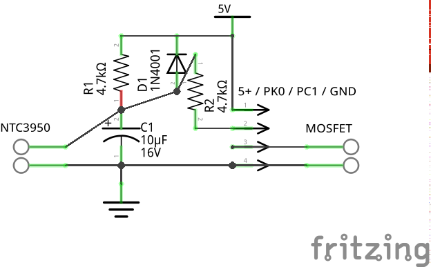
inspired by the K8800 schematics for the hotend thermistor??
Hey,
I follow these report for a view day`s! That’s great! I also build an heatbed application for the Delta.
Yesterday I scratched one of the Piezzo´s. but before I had good results by the autoleveling. My heatbed construction is quiet heavy, so I use some springs to get the weight from the Piezzo´s. And its getting just in touch with the Piezzo´s when the hetatbed is pointed. I realizing also that the best sensitivity is not to pull in the center of the Piezzo´s. quiet a bit to one side.
So can someone put a detailed picture form electronic parts and assembling on the Board, please!

@bibo yes this look quite heavy. What kind of heatbed are you using? I can see some insulating material but what is that in between that and the the metal parts? Can you show your setup from different perspectives?
Just lurked a bit around - what’s about using HPL (high pressure laminate) for the spacer?
It’s temperature resistant up to 180°C and easy to cut…
@shelxle: I use a MK2Y heatbed 120W, an ATX powersupply and a W1209 termostat layout. Isolation 12 Zoll Hotbed Thermal Pad Isolationsschaum.
So i bought a Hotbed Mos V1.0 NTC 3950, but thats not installed. can someone help me with informations, please?
Where did you solder the cabels exactly. And do you use some aplications between Pins on Vertex board and Sensors ( like a pullup/down´s)?
Connect the ADC8 aka PK0 directly to the NTC or like here[quote=“SurviKnows, post:1, topic:29826, full:true”]
1 Like


@bibo Thank you for sharing that information. I’m still waiting for my MK3 heatbead. But I think I will solder it to +5V GND PC1 and PK0 as shown in @Dr_Vegetable post Building a Heatbed for K8800 and pullups like in my post above. I will post some pictures when I’m done with it.
@shelexle: Im very interested!
I also get the Cracked LCD picture shown.
So as i ad in Ardoino Libraries the U8lib from the Vellemann Marlin folder it works like bevore!
You have to install it, like in File C:…\Vertex-Delta-Firmware-master\U8glib\extras\INSTALL.
But i don´t hit the line from the end of this text line!
1 Like
Be careful tapping power off of those pins. The 15V/4A might be labelled as an INPUT requirement, and may not be indicative of the reserve power that can be tapped off of the board.
At a minimum, you should determine whether those pins are connected directly to the supply voltage terminals, or whether they are connected after any voltage regulators on the PCB. (My bad for not figuring this out when I had mine apart.)
Of course, I don’t plan to take any significant power out of the K8800 board. The +5V is just for the pull up resistors for the NTC3950. PC1 pin goes directly to the MOSFET input which gets its power from a 350W power supply. To be more clear I mean soldering to pins called “SK2 9x2 pinheader” in the schematics.
So here is my soldering of the main board:


here I also added some heat sinks to the stepper drivers and atmega:

after firmware changes I’m still waiting for my Mk3 heat bed:


here are my changes to the firmware (< mine >original)
pins_K8800.h
< #define TEMP_BED_PIN        8
< #define HEATER_BED_PIN 36

Configuration.h
< #define TEMP_SENSOR_BED 13//cheap 3950
> #define TEMP_SENSOR_BED 0
< #define PIDTEMPBED
> //#define PIDTEMPBED
<   #define DELTA_HEIGHT 311.000 // I will reduce this when the heat bet is installed...
>   #define DELTA_HEIGHT 308.000 // get this value from auto calibrate
and I will try this:
Configuration_adv.h
< #define BABYSTEPPING
> //#define BABYSTEPPING
<   //#define BABYSTEP_XY              // Also enable X/Y Babystepping. Not supported on DELTA!
>   #define BABYSTEP_XY              // Also enable X/Y Babystepping. Not supported on DELTA!
<   //#define DOUBLECLICK_MAX_INTERVAL 1250 // Maximum interval between clicks, in milliseconds.
>   #define DOUBLECLICK_MAX_INTERVAL 1250 // Maximum interval between clicks, in milliseconds.
< #define PINS_DEBUGGING
> //#define PINS_DEBUGGING