Building a Heatbed for K8800

Hi guys,

First of all: I really love the K8800, I got it at a really good price and the print results out of the box are pretty good. The overall approach that every part can be easily repaired or exchanged was exactly what I was looking for.

However, from my opinion the bed levelling with piezo sensors is from time to time a weak point. After some weeks my Buildtak is full of scratches, more or less useless in case you want a good first level. (no clue why but sometimes the nose is crushed into the bed and the printer doesn’t stop moving until I pull the plug, sensitivity changed in all directions).

Anyway that’s a different story – right now, I am trying to build a heat bed because especially with PETG I am facing from time to time some warping effects. PLA without buildtak is also tricky, tape (not the blue tape – this really doesn’t work at all in my case )+ hairspray etc. works most of the cases but its not a perfect solution.

I bought a cheap MK3 round heat bed with ALU plate (~15€), build an Arduino based temperature control with a 100K NTC – no problem so far, maybe except for quite expensive 120W power supplies.

Obviously, now we are coming back to the piezo sensors. I couldn’t find information at which temperature they still can work but so far, I didn’t dare to place the heat bed directly on top of these at max temperature. I don’t plan to print ABS, so the max temperature I am looking at is 60-70 °C for PETG. I tested up to 30-35°C and it feels like the piezos getting more sensitive at higher temperature (no idea if this is true or not).

Can you tell me the Piezo specs?

I tested some ideas but its not yet working.

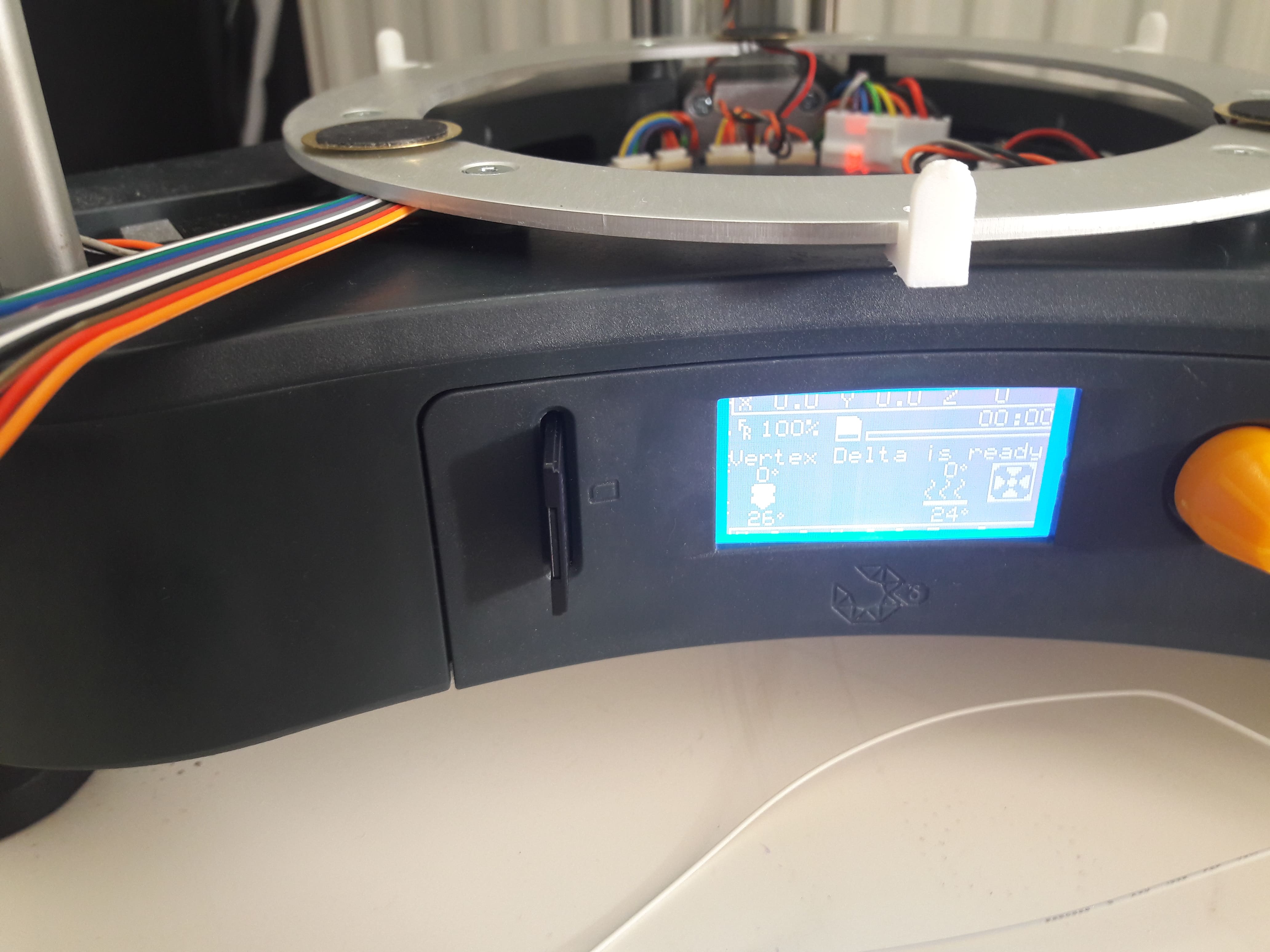
I have printed some place holders so that the heat bed is “flying” 2 cm above the piezos. Also the spacers change the diameter from 22cm (heat bed) to 21 cm of the piezo ring.

The Problem of such a solution is that the bumpers need to be tightly connected to the heatbed, otherwise the nose movement is not passed on to the piezos (and yes there are already scratched on the alu bed…). Its screwed together but when I start heating up the plate the connections got a bit lose. OK – I have printed the bumpers with PLA that might be very weak at 50°C – I have ordered some more temp resistant material (up to 130°C for my next try).

Any additional idea?

In case I cannot solve the piezo problem, I will remove the auto level function when using the heat bed. But I have one question here: How do I do a manual bed levelling? (maybe I am to stupid but I really don’t find this option in the menu)

Thanks and continue like that!

This sounds like an interesting project!

My BuildTak has also gotten marred. My solution (which works very well) is to install the glass plate upside-down and print on the bare glass surface, lightly covered with a glue stick.

I don’t know how the piezo elements will handle the heat, but I suspect you will have problems with the adhesive on the foam pads as well.

One thing you might try would be to install the original glass plate in between the piezos and the heated bead, to act as an insulator. (There may be better materials for doing this.) As long as you have solid contact though all layers of your build plate, the automatic bed leveling should still work.

I would also be surprised if you couldn’t control the bed heater (through a relay or mosfet) from an unused digital pin on the Delta controller - assuming one is available. Then you could enable the bed heater in the firmware and get fully integrated temperature control from the LCD screen.

Please share pictures and more details of this upgrade, if you would be so kind.

Hi,

I will print some new spacers during the weekend with Green-TEC Pro 130°C filament, hopefully they will be stable enough the bed leveling will work.

I will post some pictures hopefully by Sunday/Monday.

As soon as the basics will work, I plan to give the control to Marlin software.
But therefore I need to look a bit more in detail how Marlin work, what kind of circuits for NTC etc. is required to enable control.

However, I dont think its necessary, external control with 2 buttions, small display showing AS-IS and target temp works as well.

Modifying Marlin should be as simple as telling it that you have a bed heater and selecting the thermistor type from a list. You might need to configure which GPIO pins are assigned to the heater.

The physical modifications could go either way. Out of curiosity, I took the controller board out of my Delta today to see what it has for extra pins/expansion options. The good news is that the board does have two rows of pins that appear to provide access to a number of I/O pins. There is also a pair of connections that is labelled 15V 4A, which probably is not enough to run a heater off of, but at least they were thinking about expansion.

2 Likes

Hi,

enclosed some pics of the heat bed. It fully works now, no change to original hardware requried.
It can be placed on top of the regular bed mounts (in my case its not original anymore since I had to change the diameter, but anyway).
Auto Leveling works quiet good as well also it looks like its getting very sensitive when heat bed is really hot (>60°C). Anyway I turn on the heat bed in parallel to the bed leveling before printing and temperature is perfect when printings starts.
Spacers are not getting hot, so piezos are protected. They are printed with PETG, hope there is no temperature issue in future. I had some issues with high temp filament, warping as hell. But a layer of cork should give a bit of protection.


I will have a look into marlin software as well as hardware requirements (how to connect NTC - suprisingly looks like easy voltage devider at least for nose, on/off control voltage for heatbed etc.).

TIP: Dont buy the cheapest MOSFET board, it took some time to troubleshoot. All Rs are at 100K, so there was not enough current to drive optocoupler with 3,3V. Also there is no schemetic available in the internet…

1 Like

I just had a look into schematics from other MARLIN Boards to check how they drive the NTC and bed control.
Looks pretty straight forward, see RAMPs pic below. The logic to turn on/off the heatbed is anyway on the MOSFET board (3,3V capable) so it can directly connected.

(Thanks to the PCB desiger who made the decision to break out most relevant pins on the headers :slight_smile:)

I am still surprised that the NTC can be easily connected to the ATMega. Due to the variance of the NTC (100K at 25°C to somewhat 15K at 100°C) I really had some issue to program this by myself. Anyway looks like MARLIN takes care about that challenge.

Question: Where do I get the source K8800 source code from? Its still empty:


This is looking great so far! I really like the way the PETG supports are designed - very thoughtful thermal management there!

The K8800 firmware can be found here:

https://vertex3dprinter.eu/downloads/vertex-delta-downloads/

1 Like

Thanks for the links!

I had a quick look into the source code and some guide lines.
Looks like its really quite easy:

Define Pinout in the pins_k8800.h:
#define TEMP_BED_PIN 62 //PK0 Analog Input
#define HEATER_BED_PIN 36 //PC1 Digital bin
(looks like the other pins from port C are defined for something called “ULTRA_LCD”???)

In configuration.h add:
#define TEMP_SENSOR_BED 13 // “13” describes the type of NTC in my case a cheap 3950 NTC

–> Compiling test is ok.

Maybe by end of the weekend I can solder the header and connect the NTC for first testing.

If I would knew in advanced that its that easy, I would not have programmed my own Arduino…

Thanks!!

2 Likes

Cool! Yes, the Marlin firmware already knows how to do all of this, if you know how to ask.

ULTRA_LCD is an LCD display + rotary encoder + SD Card Reader design. I think all of the Velleman designs use ULTIMAKERCONTROLLER instead, so you should be OK there.

Oh, and taking the controller board out is much easier if you remove the leg of the plastic triangle housing where the USB connector goes. After you’ve removed the aluminum ring that supports the piezos, remove 4 phillips screws from the underside of the printer and just slide the whole unit up the side rails.

You might get it apart without doing that, but you won’t get it back together.

My K8800 has now a bed temp sensor :slight_smile:!

Although I do not fully understand pin numbering in Marlin yet (looks like ADC pins have their own numbering), with
#define TEMP_BED_PIN 8 //PK0 Analog Input
it works.

There is a small problem with the display, for some reason the lines are a bit rotated, the first 2-3 rows are at the bottom - however, thats not a problem for me.

The full heat bed control will be tested during weekend.


2 Likes

Nice work!

The ATMEL processor pin designations are different than the Arduino pinout designations, which causes a lot of confusion. I always have to look that up whenever I’m assigning pins.

That display glitch is strange. Is it possible that some unintended changes crept into your source code? Something else I always ask after new firmware behaves oddly: did you remember to run M502 and M500 after you updated the firmware? (You will need to recalibrate after doing that.)

Also assuming you used Arduino IDE 1.0.x, etc…

Again, nice work!

The display issue is most likely related to U8glib.

The included source code U8glib version causes a Arduino Compiler error so I used the latest U8glib directly from Arduino lib manager. (known issue?)

What version of the Arduino IDE are you using? Newer versions may not be compatible.

I am using 1.8.15 - somewhere in the Marlin code its written that it does not work with 1.0.xx …

I have flashed the firmware with Arduino IDE 1.6.8 with original,included U8glib - now display problems are fixed :slight_smile:!

I guess I will report the problem somewhere

1 Like

@SurviKnows, where did you find the schematics for the K8800 board?

And, can you share your .stl for the supports?

Here you go :wink:

:see_no_evil:
Sems it was to obvious to look at that Place…
Thanks!

@SurviKnows
This looks great! Can you please give us the information what parts are needed and probably were to get them? Is a second Arduino required or does the K8800 board all the magic? Thanks!

From my playground:

  1. power supply 12/24V, ~200VA
  2. MosFET shield (I used this one, it has an opto coupler as input, seems happy with 3.3V outputs) https://de.aliexpress.com/item/1-st-ck-3D-Drucker-Teile-Heizung-Controller-MOS-Modul-MKS-MOSFET-Bord-Heatbed-Extruder-30A/32831612566.html?spm=a2g0s.9042311.0.0.42164c4dJuOJAH
  3. some kind of head bed (Kossel >=200mm diameter)
    maybe this one will fit… https://de.aliexpress.com/item/3D-Drucker-Heatbed-Aluminium-Heatbed-mit-kabel-f-r-Kossel-Delta-Plus-Pro-DIY-Auto-Nivellierung/32837491920.html?spm=a2g0s.13010208.99999999.266.6a783c004fXBMW
  • You don’t need an additional Arduino if you recompile Marlin with the receipe from @SurviKnows
  • attach MosFET shield to K8800 mainboard

I already did steps 1 and 2. Instead of Kossel headbed I used a silicone headbed (160mm) directly glued to the K8800 glass bed. Problem hereby is the major temperature difference betweeen center and outside of the bed ( >20°C difference).

1 Like