Thanks for your idea. This greatly improves the z-Axis of the prints, as you can see in the following photo. On the left a print before replacing the motor holder, on the right side the results with the new holder. No replacement of the axis/motor shaft coupling. In the middle a M5 normal screw.
I redesigned your holder in openSCAD because i want to use M3 nuts and bolts to assemble the two parts. The openSCAD files can be found on thingiverse.
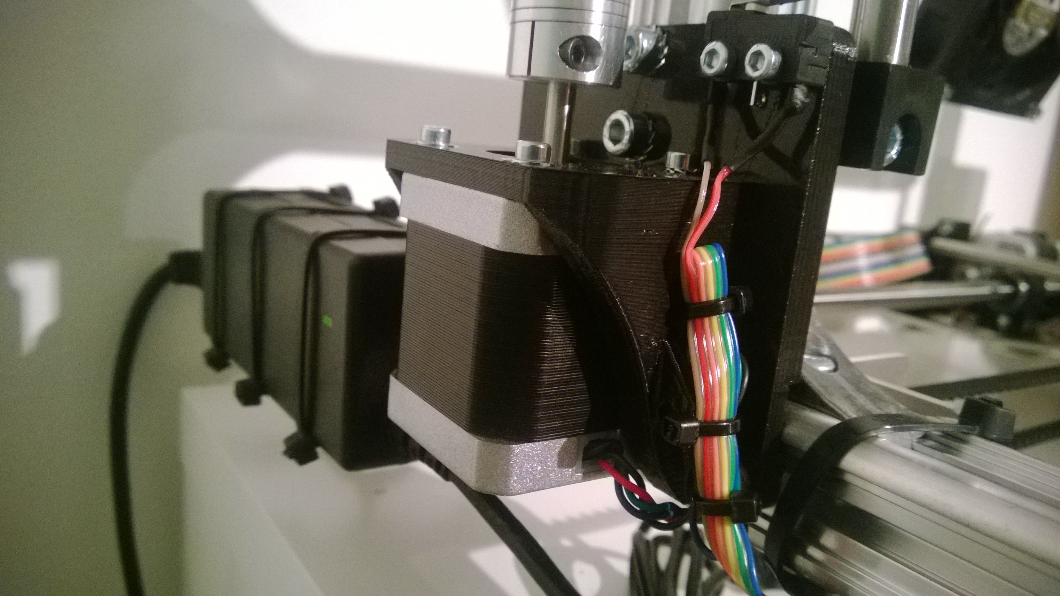
And this is my interpretation of the design from edirol as photo. I put the screws that bolt the assembly to the vertical frame a bit higher, so that the motor axis is not in their way. This made the assembly easier.
Actually no reason. I only had one screw and it worked. In the design there are two holes for the switch screws (they should fit). And another sloppyness is visible on the photo. I did not isolate the wire extension for the switch (i ran out of shrink tube). In the package where not enough for the printer in the first build and i did not yet get more of the small tube. It is not that of a problem, since the wire does not move. I will isolate it when i get to the store for that type of stuff.
The bend of the lever is from the previous mount (i did position the motor very low on the profile and the long screw of the end stop was “too short”). Now the screw hits close to the actual switching knob. I think that is better. It takes a bit of the risk of the long flexible moving lever and a misplaced z-level.
In the version from mstolt the z-axis bearing assembly hits the base plate of the design. The endstop screw is too short or either the base plate is to high. The assembly for connecting the base plate with the motor holder (M3 screws and bolts) is perfect in this version. On the other hand the base plate design from endirol is perfect. A perfect solution for this issue would be to combine the endirol design with the assembly screws and bolts from mstolt. Both designers have done a good job and they could do even better with combined effort.
Nice design from both mstolt and endirol. This proposed design would be beneficial to more K8200 users!
Hi motoritz and czvt7w,
even though it is obsolete with the new design from edirol i updated the design on thingiverse with a shorter (12mm shorter) version of the baseplate. Sorry for the misprints. I use a mounted mirror on top of the print bed. That makes the additional height.
But with edirols design improvement it is obsolete.
Hi,
I am currently mounting my new k8200 and following your suggestions I directly mounted the last version of your plate/holder (using another 3D printer!). everything looks great so far.
concerning the problem of possible misalignments of the rod with the motor axle, I though of using an Oldham coupler.
by mistake I first ordered one piece only (the one that fits the motor) but I have checked and looks to fit well wit the rest of the assembling, though I suspect that some readjustment of the level of motors etc could be needed.
if it could be useful, these are the 3 parts that should be needed:
yes I think that both work, however in principle a “flexible” coupler works better if the two axles are at an angle, whereas the Oldham coupler works better if the axles are out of center, as is more likely to be the case (additionally, the Oldham coupler can also accept a slight angle).
have now a m10x 1.25 and a bronze nut
al vibration and wobble is gone
had to fill up the top bearing holder between the aluminum support
to get the axis parallel to the aluminum profile +/- 0,3mm


 Yours is clearly more charming in form.