The Solution for all your Delta woes

I have had a Delta for less than a week. Like others here, I’ve had some challenges getting the printer to work reliably. At some times everything would work great, then it would suddenly stop getting good first layer adhesion, or the belts would start skipping teeth. So I was tinkering with it when I saw a comment from Velleman about letting the brass bushings break in “like a new engine.”

I have been applying “3-in-1” oil to the bushings and wiping away the black sludgy residue from the vertical rods. I could tell that the bushings were not sliding quite as smoothly as they should.

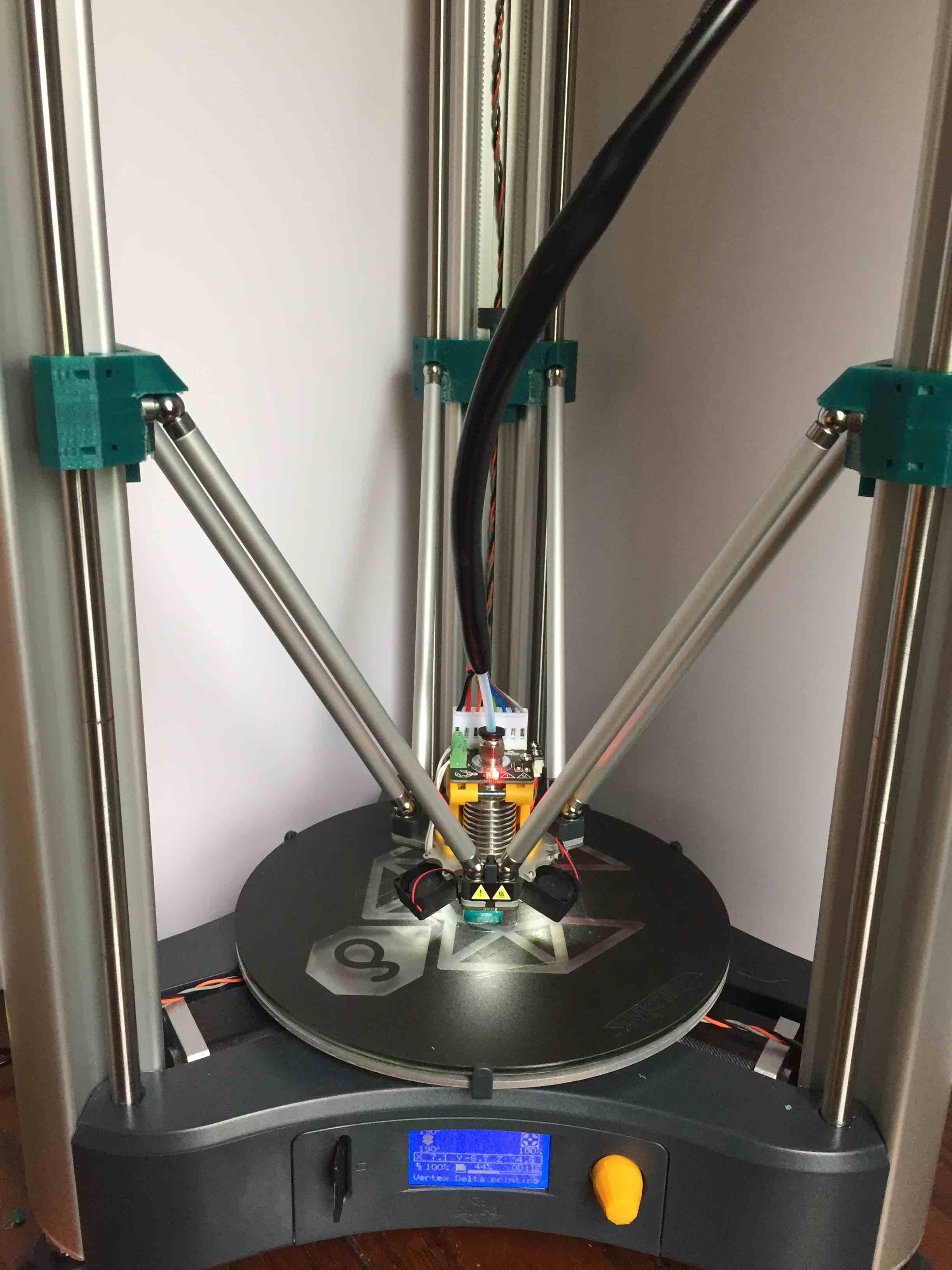
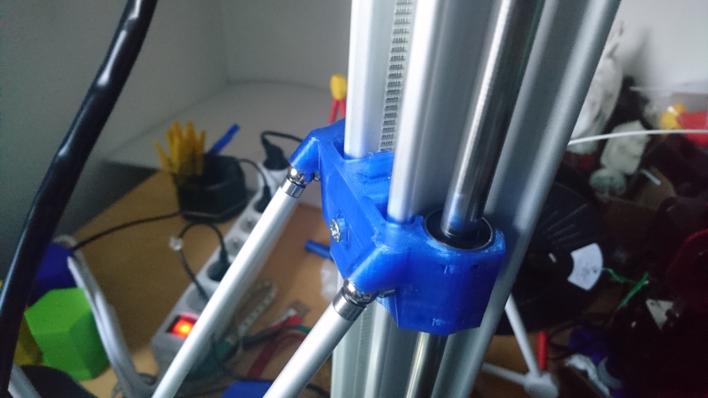
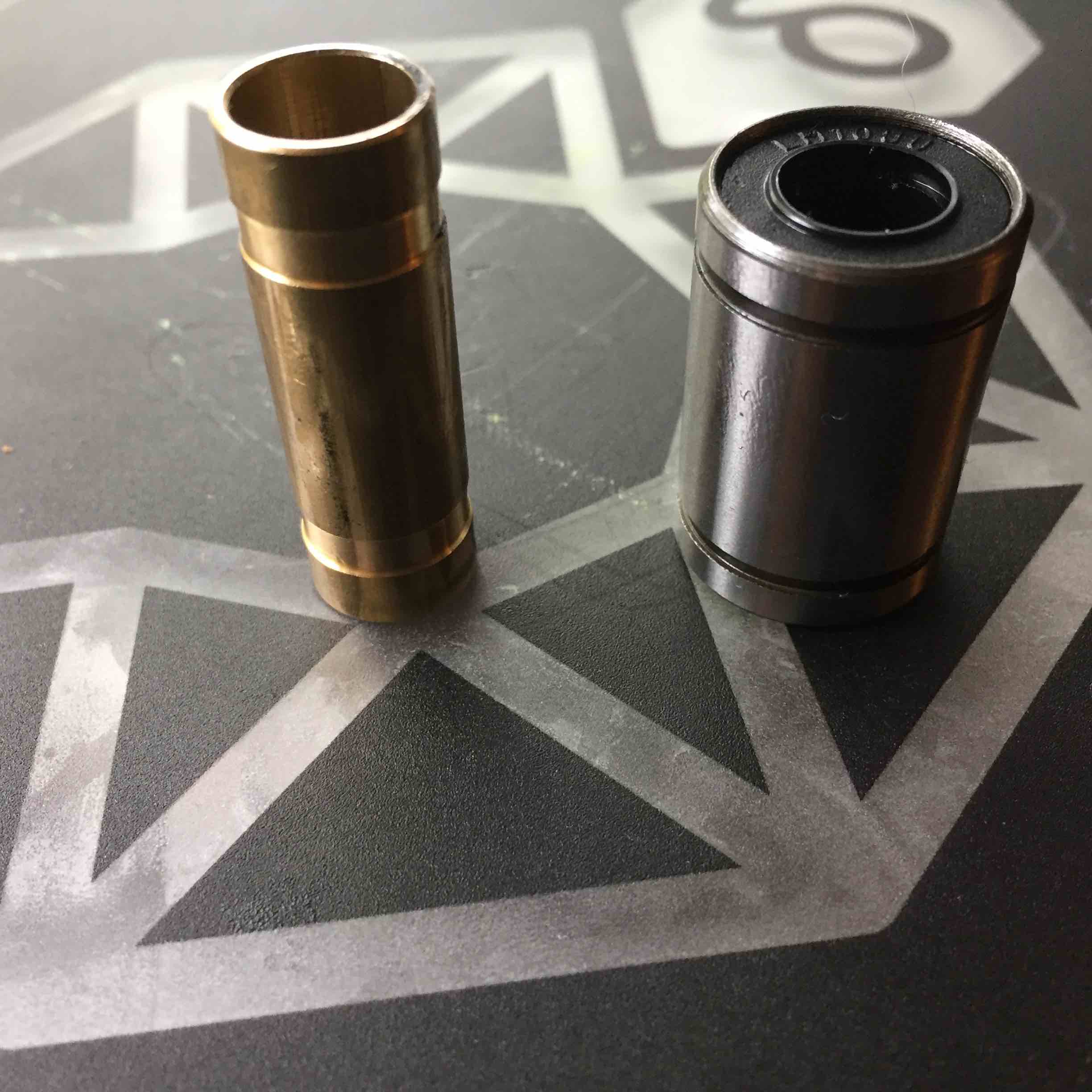
I considered using some brass polish to try to help the bushings break in more quickly, but instead settled on a different solution. I replaced the brass bushings with LM10UU linear bearings. (These are used in the K8200 kit on the lower rods in the X-Y Table assembly.)

There were a few complications in doing this, but it was primarily a matter of removing the top plate from the printer and swapping them out. The initial results are promising. The printer is already noticeably better at getting a good first layer, which has resolved the skipping belts and thrown rod problems as well.

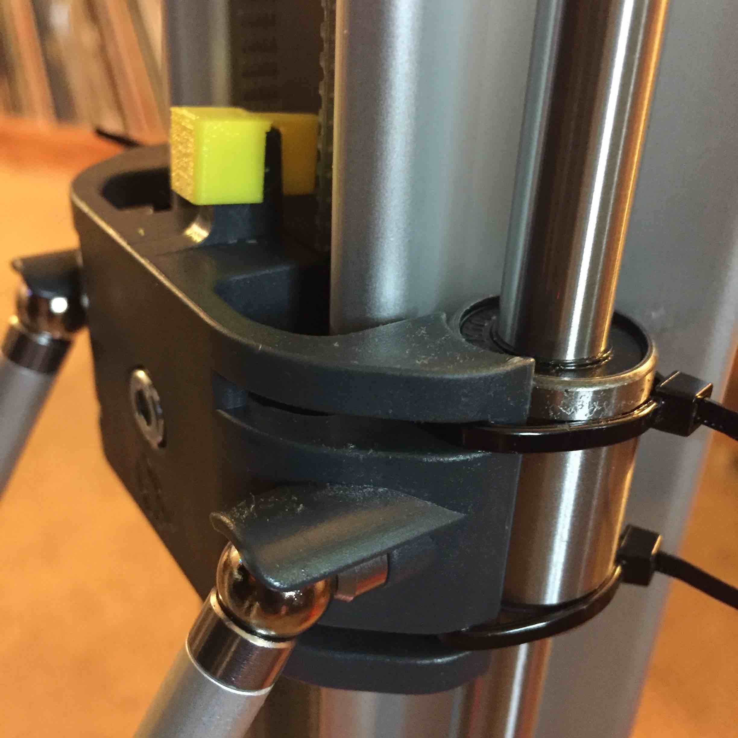
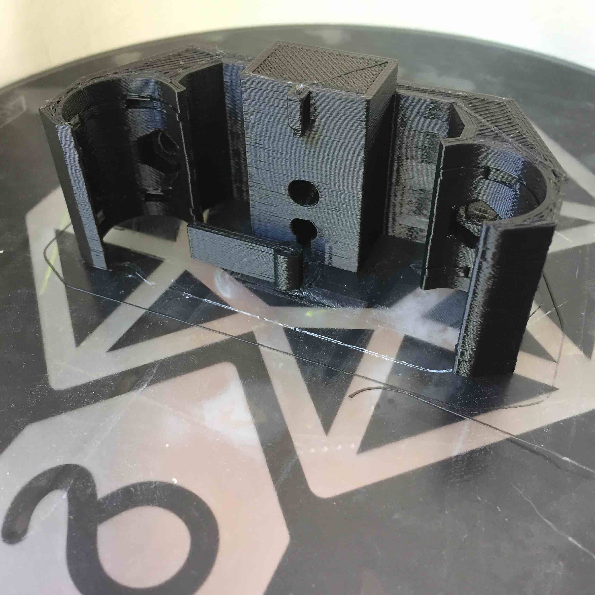
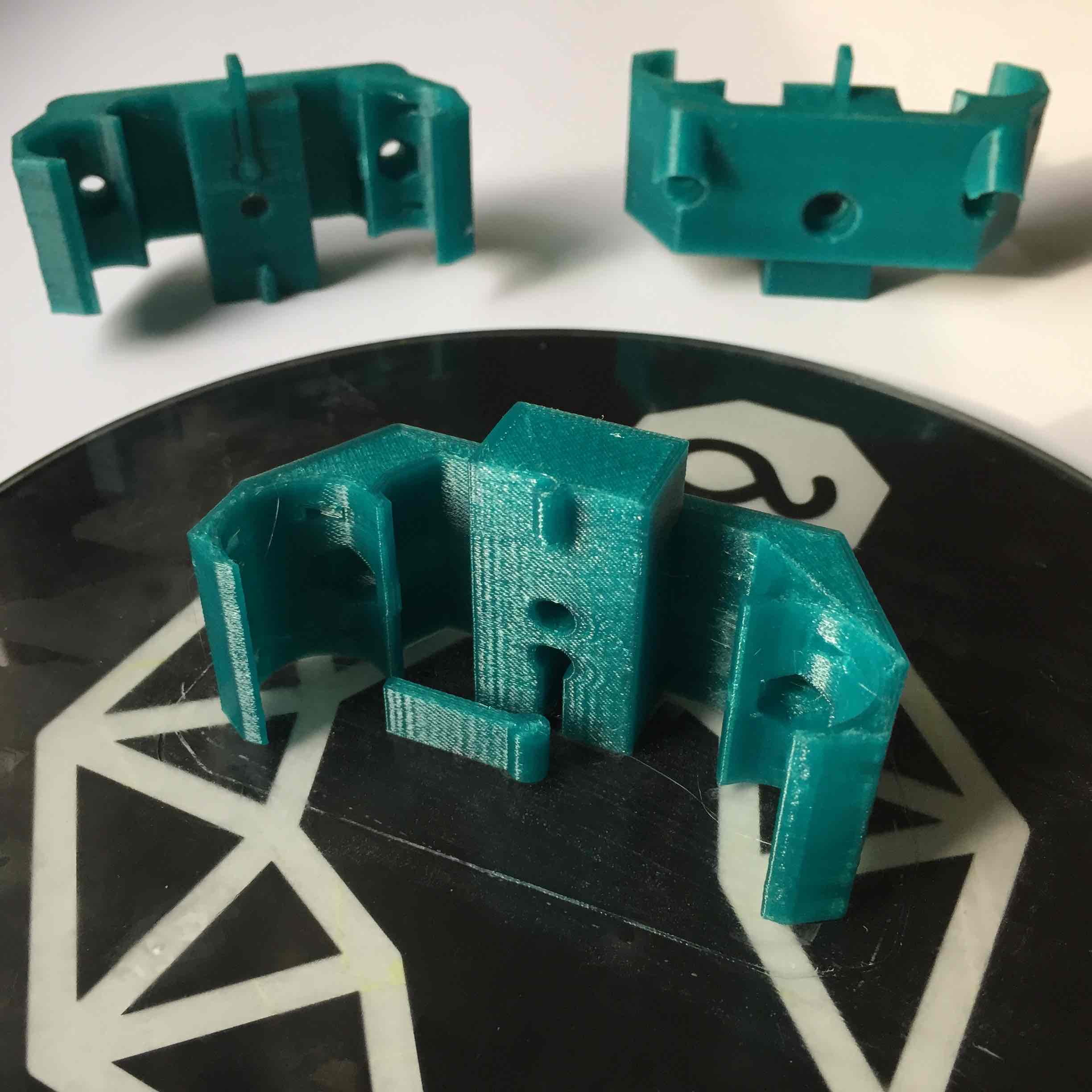
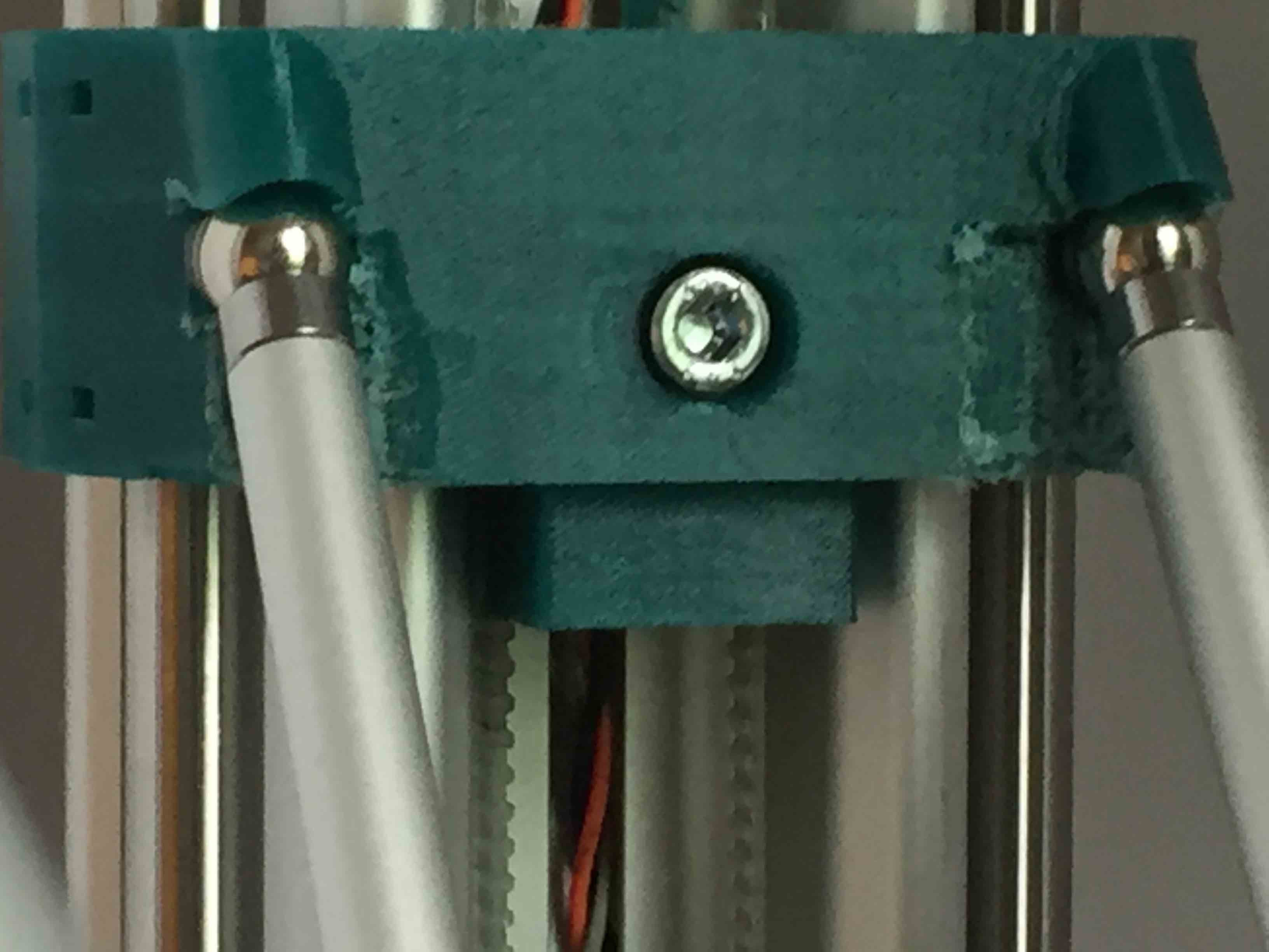
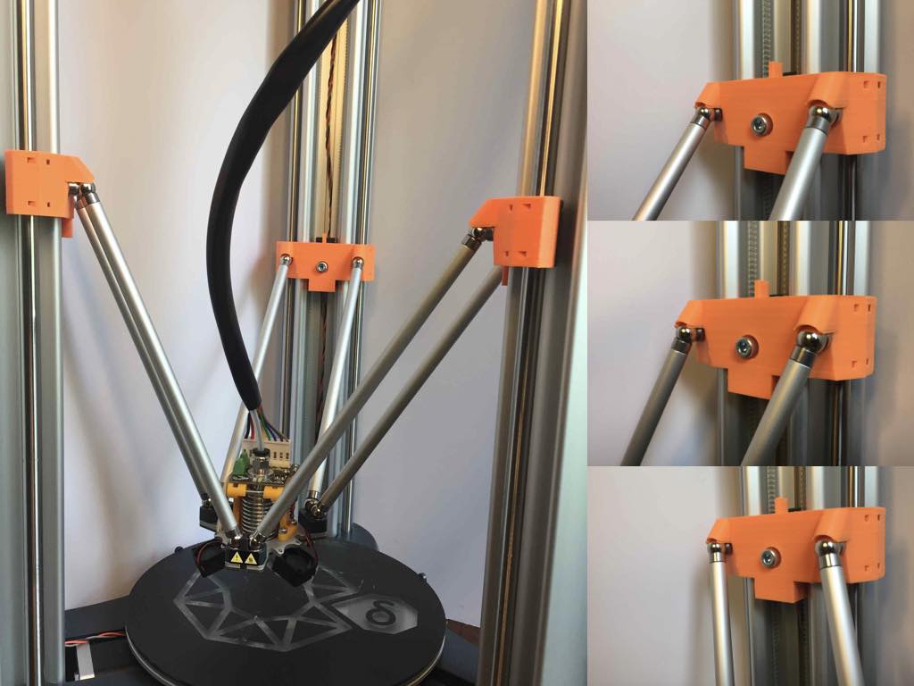
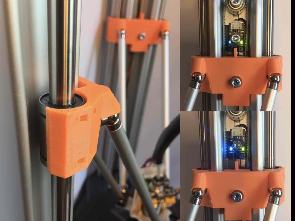
As you can see from the pictures, the LM10UU is not the same physical dimensions as the stock bushing. I was able to secure it to the sled with tie-wraps, but this also changed the geometry of the printer slightly.

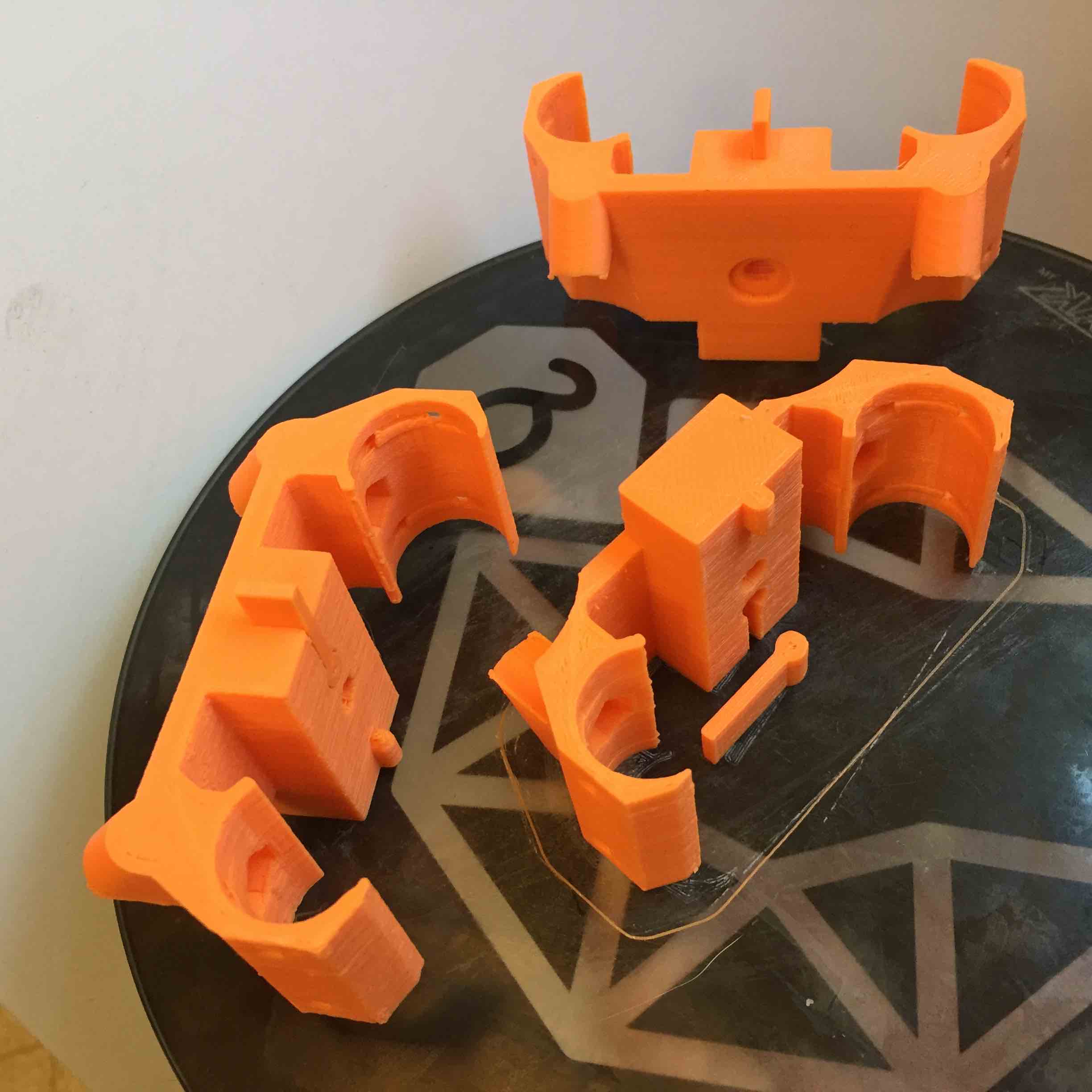
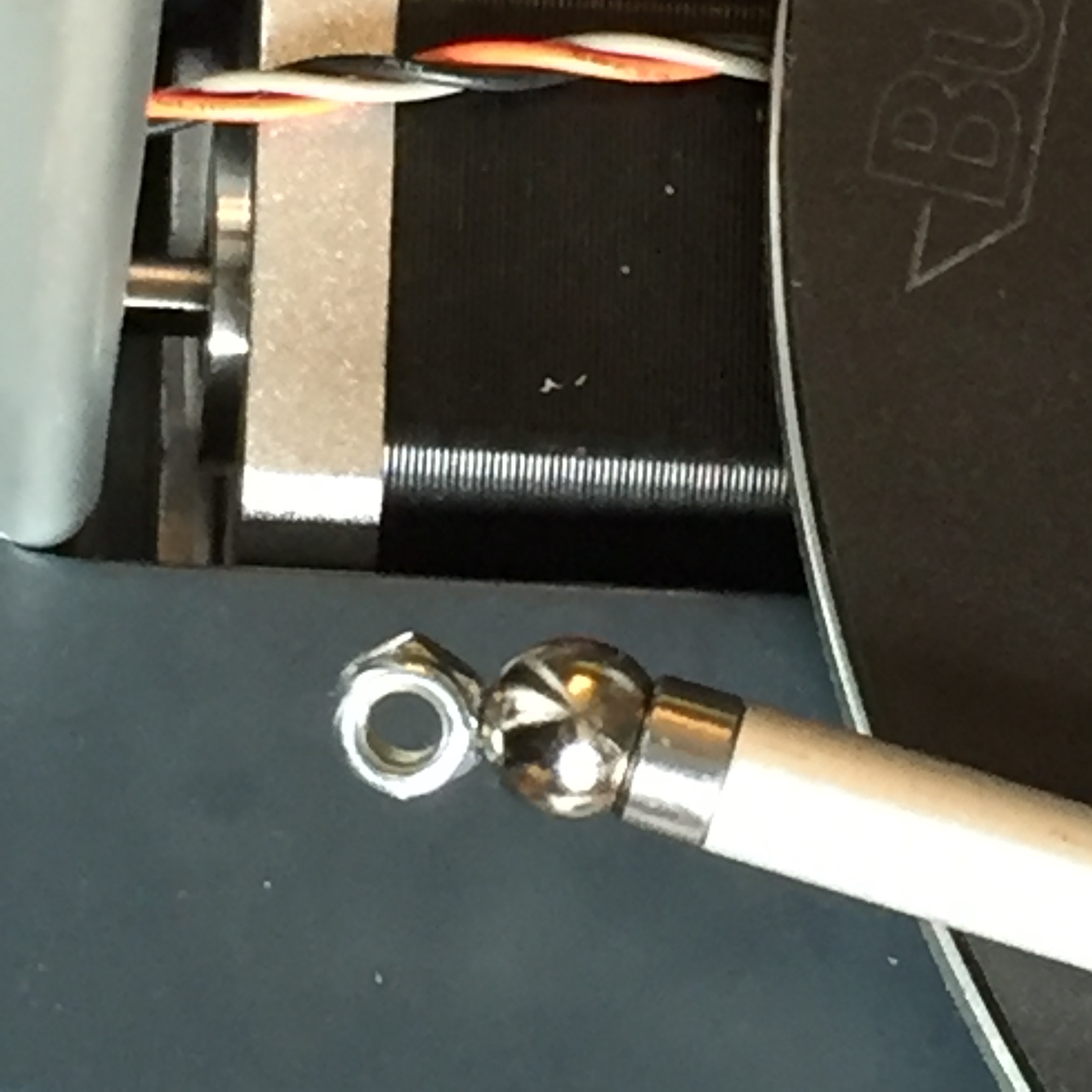
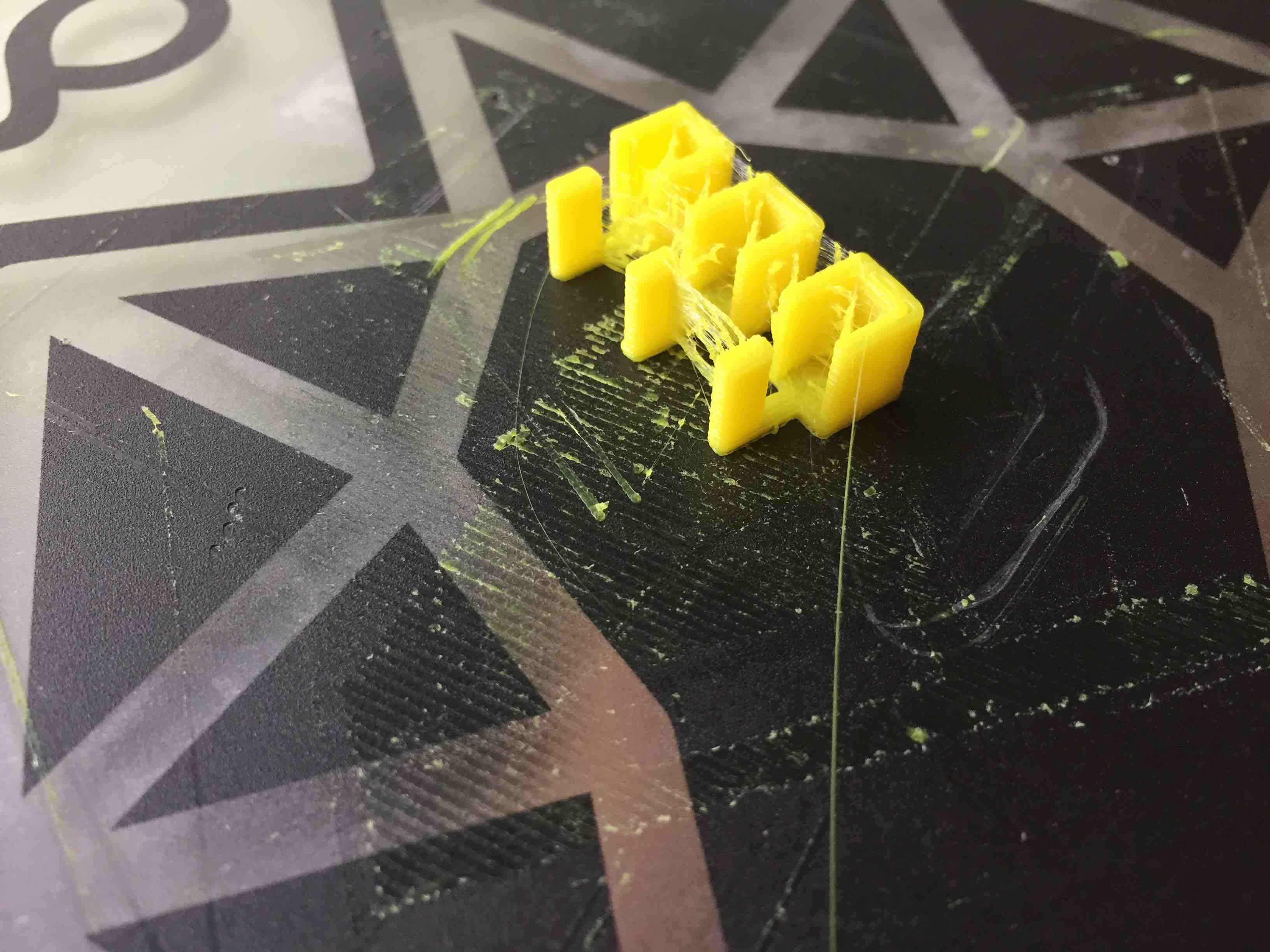
One consequence of this was that I needed to extend the limit switch actuator a few cm. At first I just used small pieces of black electrical tape, but then I printed some small tabs to do the job.

I did not bother to change the Marlin firmware to account for the geometry change, but it appears to be a simple change to one measurement in Configuration.h. I found that the printer was able to auto-calibrate and print without this change, though I suspect the dimensions will be slightly off until I correct the carriage offset value.

If you don’t want to go to all this trouble, my advice is to oil the brass bushings and wipe the rods clean before every few prints while the printer is breaking in, and be patient with it.

2 Likes

I have made some improvements to the linear bearing upgrade.

I was not satisfied with the slight reduction in build radius caused by the poor fit of the new bearings into the existing K8800 sled, so I set about designing a new part that would fit better. My design goals were:

1.) Fit LM10UU linear bearings, with minimal reduction in build radius.
2.) Easily printable without supports
3.) Maximize vertical build height

I went through three iterations on this design. The first one, printed in black PLA, did not fit properly, but allowed me to test and tweak a few critical dimensions on the piece. (Note the thermometer-shaped endstop actuator tab, which is inserted into the slot on the carriage after it is printed.)

The next iteration (green PLA) fit well, but there was interference with the connecting rods at extreme print angles.


I was able to butcher the pieces on my drill press to remove the offending material and get the parts to work. But a third version was clearly in the cards…

The third iteration on the design moves the rod anchors to the top of the carriage, gaining a few extra millimeters of vertical build space. These are currently installed on my delta, and are working well.

I am still making some final edits to the carriages, and I will post the design to Thingiverse when they are done.

PRO TIP: When working on the K8800, I seem to always drop nuts and bolts down into the well where the stepper motor resides. After a few times of having to flip the printer over and (gently) shake it to get the parts back, I realized that the magnetic connecting rods are the perfect recovery tool…

1 Like

Check for full range of motion without interference:

Verify endstop functionality:

And the good news is that this modification doesn’t require any changes to the firmware.

I noticed that Velleman left the M503 command enabled in the firmware, which is a very useful diagnostic tool. Examining the console output from M503, I was able to verify that the Automatic Calibration procedure will detect and correct for the change in radius to the build area. From my measurements beforehand I expected to lose about 3mm from the radius, and was pleasantly surprised to see that the calibration did this for me.

If you aren’t familiar with M503, you will want to learn about it. It works in conjunction with M500, M501, and M502 to manage your EEPROM and SRAM configuration settings. M503 reports all current SRAM settings (the ones that are currently in effect) in a format that provides the necessary G-code to change each parameter.

http://marlinfw.org/docs/gcode/M503.html

This upgrade seem to be working well, so I published the STL files for the carriages to Thingiverse. Enjoy!

3 Likes

Dear Dr Vegetable,

what are you long time experiences with your improvement? Are you still using it? I’m thinking about to replace my original parts with this.

1 Like

I changed the brass bearings against Polymer bearings (Igus Drylin RJ4JP-01-10). They are much lighter than the steal bearings suggested by @Dr_Vegetable.
I did’nt build the sleds, I simply mounted them with zip ties. So, the upper mounting moved approx. 3mm to the center. But I didn’t have any problems 'til now.
(I have to admit that I didn’t check tolerances in printout - ait least I didn’t notify any.)

When using @Dr_Vegetable’s sled, you have to remove the brim inside the sled, because the top/bottom groove of the bearing is much smaller than the steal bearings one.

(@Velleman - it would really be a cool enhancement to offer sleds with either polymer or steal bearings - no need to burnish the brass one’s anymore and feel like a steam engine machinist)

1 Like

Please someone help me.
I made the LM10UU sleds and auto calibrate the printer now the nozzle can’t be moved below 2.6mm above the glass plate. Here some outputs of M503 M114 M119 M211:
07:54:43.227 : echo:DEBUG:INFO,ERRORS
07:54:43.227 : echo:Active Extruder: 0
07:55:26.393 : echo: G21 ; Units in mm
07:55:26.393 : echo: M149 C ; Units in Celsius
07:55:26.393 : echo:Filament settings: Disabled
07:55:26.393 : echo: M200 D1.75
07:55:26.393 : echo: M200 D0
07:55:26.393 : echo:Steps per unit:
07:55:26.393 : echo: M92 X116.36 Y116.36 Z116.36 E148.70
07:55:26.393 : echo:Maximum feedrates (units/s):
07:55:26.393 : echo: M203 X500.00 Y500.00 Z500.00 E25.00
07:55:26.393 : echo:Maximum Acceleration (units/s2):
07:55:26.393 : echo: M201 X9000 Y9000 Z9000 E10000
07:55:26.393 : echo:Acceleration (units/s2): P<print_accel> R<retract_accel> T<travel_accel>
07:55:26.393 : echo: M204 P3000.00 R3000.00 T3000.00
07:55:26.408 : echo:Advanced: S<min_feedrate> T<min_travel_feedrate> B<min_segment_time_ms> X<max_xy_jerk> Z<max_z_jerk> E<max_e_jerk>
07:55:26.408 : echo: M205 S0.00 T0.00 B20000 X20.00 Y20.00 Z20.00 E5.00
07:55:26.408 : echo:Auto Bed Leveling:
07:55:26.408 : echo: M420 S0
07:55:26.408 : echo:Endstop adjustment:
07:55:26.408 : echo: M666 X0.00 Y-0.39 Z-0.49
07:55:26.408 : echo:Delta settings: L<diagonal_rod> R H S<segments_per_s> B XYZ
07:55:26.408 : echo: M665 L207.00 R107.70 H310.57 S60.00 B50.00 X-0.44 Y-0.21 Z0.00
07:55:26.408 : echo:Material heatup parameters:
07:55:26.408 : echo: M145 S0 H200 B70 F255
07:55:26.408 : M145 S1 H250 B100 F255
07:55:26.408 : echo:PID settings:
07:55:26.408 : echo: M301 P15.20 I1.75 D50.42
07:55:26.408 : echo:LCD Contrast:
07:55:26.408 : echo: M250 C32
07:55:26.408 : echo:Z-Probe Offset (mm):
07:55:26.408 : echo: M851 Z0.00

07:57:29.960 : echo:enqueueing “M665 B50”
07:57:29.960 : echo:enqueueing “G33”
07:57:29.976 : G33 Auto Calibrate
07:57:36.434 : Checking… AC
07:57:36.434 : .Height:310.57 Ex:+0.00 Ey:-0.39 Ez:-0.49 Radius:107.70
07:57:36.434 : .Tower angle : Tx:-0.44 Ty:-0.21 Tz:+0.00
07:57:51.457 : Iteration : 01 std dev:0.014
07:57:51.457 : .Height:310.59 Ex:+0.00 Ey:-0.41 Ez:-0.48 Radius:107.73
07:57:51.457 : .Tower angle : Tx:-0.42 Ty:-0.15 Tz:+0.00
07:58:12.720 : Calibration OK rolling back.
07:58:12.736 : .Height:310.60 Ex:+0.00 Ey:-0.39 Ez:-0.49 Radius:107.70
07:58:12.736 : .Tower angle : Tx:-0.44 Ty:-0.21 Tz:+0.00
07:58:12.736 : Save with M500 and/or copy to Configuration.h
G0 X0 Y0 Z1
M114
08:01:33.305 : X:0.00 Y:0.00 Z:2.60 E:0.00 Count X:20570 Y:20570 Z:20570
M119
08:04:31.212 : Reporting endstop status
08:04:31.212 : x_max: open
08:04:31.212 : y_max: open
08:04:31.212 : z_min: open
08:04:31.212 : z_max: open
08:04:31.212 : filament: TRIGGERED
M211
08:06:51.727 : echo:Soft endstops: On Min: X-100.00 Y-100.00 Z2.60 Max: X100.00 Y100.00 Z310.60
08:11:05.013 : X:0.00 Y:0.00 Z:236.89 E:0.00 Count X:47831 Y:47831 Z:47831

Do I need to change the fimware or does M665 with some flags do the job?

I didn’t change the firmware…
Your tower angle doesn’t look so good…

That’s what I get when I run the automatic calibration (original sleds with Drylin RJ4JP-01-10):

Calibration OK rolling back.
.Height:303.09 Ex:+0.00 Ey:-1.16 Ez:-2.24 Radius:106.43
.Tower angle : Tx:-0.23 Ty:-0.05 Tz:+0.00

And that are my results:
G0 X0 Y0 Z1
M114
X:0.00 Y:0.00 Z:1.00 E:0.00 Count X:21347 Y:21347 Z:21347

How did you test and set your max. acceleration / max. feed rate?
I only see
M203 X400.00 Y400.00 Z400.00 E25.00
M201 X3000 Y3000 Z3000 E3000

Thank you!
My default max feed rates and accelerations are the factory defaults defined in Configuration.h
#define DEFAULT_MAX_FEEDRATE { 500, 500, 500, 25 }
#define DEFAULT_MAX_ACCELERATION { 9000, 9000, 9000, 10000 }
I never changed them so far.

I think my problem is that the ‘height’ is now greater than 310.
I need to look if I saved a previous M503 on my PC at home.

So, why don’t you move the endstops a 5mm down?

Hmm, once I did a “restore secure settings” - maybe that’s the reason…

Yes that would have solved the problem too.
I just made a little change in the firmware:
#define DELTA_HEIGHT 308.000
to
#define DELTA_HEIGHT 311.000
It prints fine now. The only thing is that it is much louder while fast moves.

Wow much is the weight of Igus Drylin RJ4JP-01-10?

Weight is approx. 6g

1 Like

Thank you. This is much less and a bit less than the LM10UU and the original brass bushings. I think I will consider using them. For now the LM10UU work fine.

Hi, new to the forum but would like to try and print the carriages for the LMU10 bearing but the thingiverse file does not open. is there perhaps another way to obtain the stl files

You can try out the Github repository of @SusisStrolch

Velleman_K8800_Delta_LM10UU_Linear_Bearing_Upgrade

Dear Dr Vegetable,

I print carriages very similar to yours. They also can receive LM10UU linear bearings. And now my printings are going well without oiling every time. Thanks for this so good idea.

But I got one problem. My printings are now about 4% to large in X and y axes.

Could help me to solve it? The only way I found is to modify the parts scales in Cura.
Auto calibration doesn’t make any change as I can see.

Same problem here, the LM10UU bearings are working great, much smother.
But prints are about 4% too large on X and Y only.
Auto calibration didn’t change this.

Hi @Grendel083

Print mine bearings with the old bearings, and you got no problems anymore, lighter,
and no problems anymore, use those now for 9 months.

Kind regards,
Tom