MK178 verification and modification

Good morning,

I bought and assembled this circuit but I would have some questions:

  1. why, despite following the instructions to the letter, my circuit differs from the photo found on the web (resistors and jumpers)

  2. it is possible to change the frequency of the flashing (due to the inertia of incandescent lamps, the flashing is not very visible)

  3. How come the “flash repeat interval” (without jumper) for a new activation takes more than 15 seconds instead of 7.

Thank you
Max


hole taken from the web

this is my circuit

You’ve placed the shunts incorrectly, you’ll need to place them vertically.
Otherwise they the rest looks OK.

The resistor may look different due to different suppliers. They are still functionally OK.
The same for the jumpers.

Unfortunaly the frequency can’t be changed. That’s preprogrammed

Thanks for the answers …
the resistances I had also checked with the multimeter but correspond to the instructions.

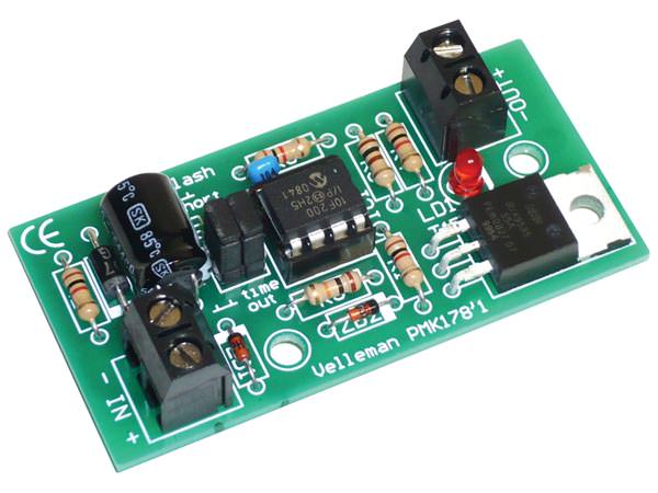
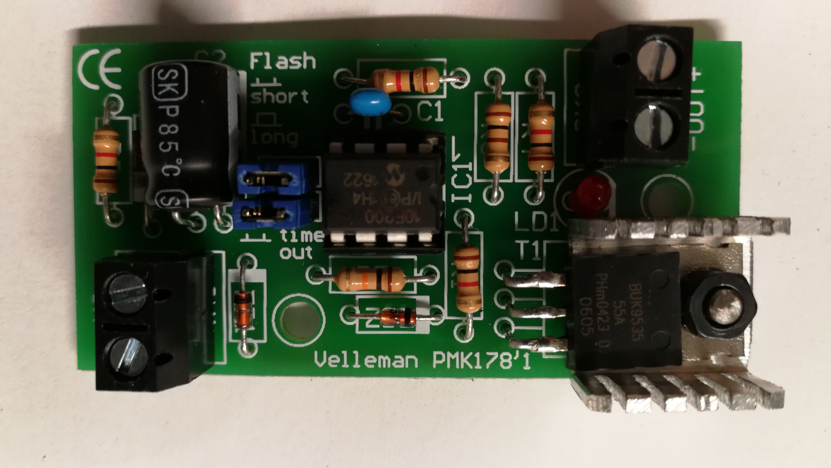
Regarding the jumper (or shunts) I will try to turn them … but the instructions and the screen printing are indicated as I placed them (you can also see from the picture - my circuit is the one with the heatsink)

hmm yes
Seems like counter intuitive.
I’ve checked now on the PCB and you’re right they need to be placed horizontally

Good, perfect, thank you !!!

What can be the explanation that the “pause” time before the new flash is over 15 seconds instead of 7 seconds ???

It was the number 3 question of my first post that did not have an answer.

Thanks

Good morning,

nobody is able to tell me why the recovery time is 15 seconds instead of 7 ???

Does this pause time depend on the software on the chip or depends on a resistance / capacitor group ???

Thanks

Good morning,

nobody can answer this question ???

What can be the reason why you have to wait 15 seconds (instead of 7) to have the blink again by operating the brake pedal ???

Thank you

Hello…

nobody can answer this question ???

What can be the reason why you have to wait 15 seconds (instead of 7) to have the blink again by operating the brake pedal ???

Thank you

hi can you post a picture of the bottom side?

thanks!

Here attached…

Here … I inserted the image requested above.

PS. the use of this forum is unusual and not so immediate, I apologize for the double post

All looks good…

You can return the MK178 for inspection/repair to your local Velleman dealer or direct to:

Velleman Projects Tech. Dept.
Legen Heirweg 33
9890 Gavere
Belgium

I understand the problem …

however, the shipping of the circuit would cost more than the circuit itself … beyond the times that obviously lengthen a lot.

Is it not possible to have some more information or an indication of what the problem might be, so that I can check?
I’m an electronic expert even if I do not have an oscilloscope, I could do some control.
It would be possible ???
Thank you

I understand.

First of all there are no Capacitors controlling the timing.
These are for decoupling.

I suggest checking out if the jumper pins.
If you don’t place the shunt on the pins are pin 4 and 5 of the PIC still connected to ground?

Maybe the internal clock of the PIC configured incorrectly (seems very unlikely)

Best Regards,
VEL337

Hello,

Without power supply, without jumpers, pins 4 and 5 are NOT grounded. Do I also have to check the voltage of these two pins by supplying the circuit to 12V?

Is there a simple way, by means of an inter-switch, to exclude the operation of the circuit returning to the standard functionality of the stop?
Or is the only method to completely disconnect positive input and output by connecting them together?

(this function is very important for the annual review of the vehicle)

Thank you

I answered the questions in the post above, but maybe the notification of my new post has not arrived (the functionality of this forum is abnormal)

You could put a dual pole switch in parallel with the kit to override the functionality.
And yes please provide voltages when connected to the power

Connecting a dual pole switch means having to connect 6 wires lengthening them up to a comfortable point where to place the switch. This is complicated. There is no solution with a single pole connected to the positive pole or to the negative pole only?
I will repeat the measurements with a live circuit.

I checked the circuit by powering it at 12Vdc. Pin 4 and pin 5 are 5.18 Volt.

What can I check again?

Thanks!!!