It is supposed to be a direct connect for a Ramps board. From what I have read, this should work with the K8200 board, but I cannot figure out the proper way to connect it. Any links? Advice?
Thank you for the reply. I agree. I do not expect Velleman to support something that I bought from someone else and I would buy a Velleman lcd kit if it were available from a US distributor. However it is not and I already have an lcd that could work. I would appreciate any advice from the numerous posters that do not work for Velleman, some of which have written that they have successfully connected an lcd. This printer is supposed to be open source. So, Velleman could provide a connector diagram, but I don’t necessarily expect it. I would consider it a magnanimous gesture in support of the open source principle.
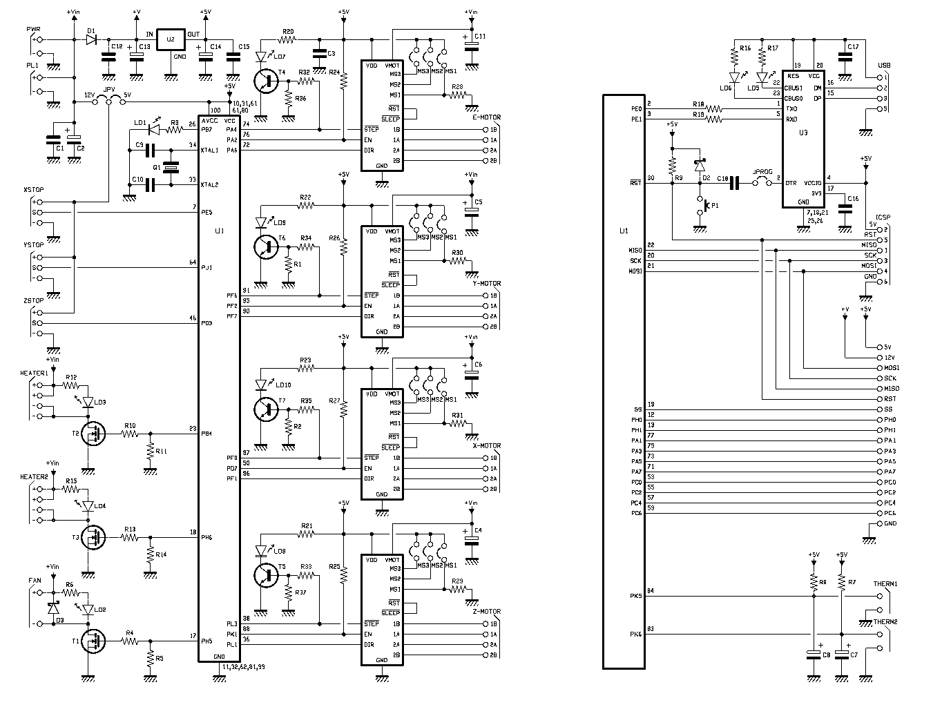
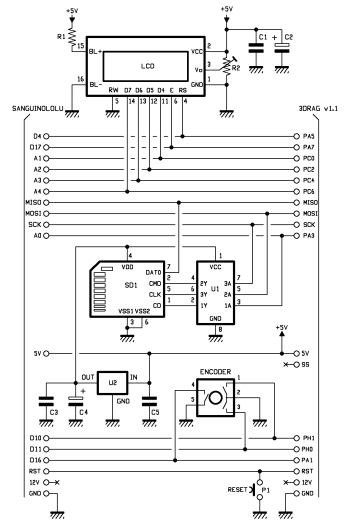
It seems that the pin descriptions are different. The K8200 describes PA,PC, and PH pins with numbers. The LCD describes the pins with a D in the range of 16-47, ie D16. I did find this link for the 3drag: http://www.open-electronics.org/wp-content/uploads/2013/07/schematics1.jpg It gives me some additional details regarding how the 3drag lcd is connected. I may be able to translate this to my lcd.
I’m worried that I know enough to give this a try, but I don’t know enough to prevent me from messing something up. I wish I better understood these pin descriptions.
that’s no schematic, at least not a readable one. Some pins can be deciphered, but others seem to be mislabeled. It’s a mess. Email them and ask for a better version of this document.
The translation is easy, you can find it in the ATmega2560 pin layout e.g. at Arduino. Some pins may have to be switched or reallocated, which is done in Marlin’s pins.h. The more important question is, whether there are enough D pins available on the K8200 board, and that’s where the schematic comes into play again: depending on how to read it, I count 10 or 12 necessary D pins, and the board has 10 to offer.
I got my lcd working. Since there has been others interested in using an lcd, here is what I did:
I am using a reprap smart controller found in numerous ebay auctions. It has a 4x24 lcd, rotary encoder, reset switch, speaker, and sd card slot. I have managed to get all but the speaker to work.
The first thing I learned is that board I purchased had the connectors backwards. In other words, pin 1 on the board is actually pin 10 on the cable for both exp1 and exp2 connectors. Since this is my only lcd, I don’t know if they are all like this. Check it closely is my advice.
The trickiest part for me was figuring out how to wire the cables. First of all, I know very little about either board and each uses different terminology to describe the pins. I could not find an 18 pin connector so I used a 20 pin to connect to the main board with two sockets just hanging in the air. Once I had my main board connector, I had to split up the other end to piece together 10 wires in the correct order for the smart controller.
Here is how you need to construct your cable:
k8200
(20 Pin connector used. If you can find an 18 pin connector delete the first two and move everything up)
I know this is now an old post but I registered here just to say a massive thank you to you “mpoore”.
I can confirm that the connections you have provided also works for the Full graphic smart controller (reprap.org/wiki/RepRapDiscount_F … Controller) . In stead of just loading Marlin V2 you have to do the following to get the full graphic display to work:
Hey mpoore could you please contact me under my email (exopex@web.de) because I have some questions (I mounted my LCD Display like you but it isn’t working right now I noticed that the current on the 5v pin is “only” 4.2V is that the error :O. The lcd keeps beeing black maybe you could take a few Pictures of your wireing and Show me 2 Points (where your pin 1 is on the board and on the lcd board so i can proove where my error is I changed the firmeware but I am not sure of my wirering
It’s been months since I did this mod, so I do not remember a lot of the details. I did save some notes, which I am using to help with my reply.
I will try to help, but I will not be able to take any pictures. I have everything in enclosures and numerous zip ties, that I would rather not take apart for pictures. My recommendation to you is to carefully test your cable to make sure you assembled it correctly and that you do not have any open circuits. I would also check for shorts between pins on the connectors. It is very easy to mess up the cable since you have to separate the wires from the ribbon to make the proper connections. Use a continuity tester for each lead and do it one by one.
4.2v should not be the problem. I don’t know for sure. Someone else might answer differently.
If you are using a 20 pin connector, which is the one I used for the main board, pins 1 & 2 will be connected to nothing. There are only 18 pins on the main board. The 20 pin connector can only be installed one way because, if I remember correctly, the fan connector prevents a 20 pin connector from overlapping in the other direction.
The lcd board connectors should be labeled EXP1 and EXP2. Pin 1 of EXP1 goes to the speaker and pin 9 is ground. Pin 1 of EXP2 goes to SD Data Out (MISO) and pins 9 & 10 go nowhere. You should be able to follow the traces to confirm.
You also must be sure your v2 firmware was installed correctly. There is a way to test this having to do with the end stops. I can’t remember, but you can do a search on how to verify.
[quote=“mpoore”]It’s been months since I did this mod, so I do not remember a lot of the details. I did save some notes, which I am using to help with my reply.
I will try to help, but I will not be able to take any pictures. I have everything in enclosures and numerous zip ties, that I would rather not take apart for pictures. My recommendation to you is to carefully test your cable to make sure you assembled it correctly and that you do not have any open circuits. I would also check for shorts between pins on the connectors. It is very easy to mess up the cable since you have to separate the wires from the ribbon to make the proper connections. Use a continuity tester for each lead and do it one by one.
4.2v should not be the problem. I don’t know for sure. Someone else might answer differently.
If you are using a 20 pin connector, which is the one I used for the main board, pins 1 & 2 will be connected to nothing. There are only 18 pins on the main board. The 20 pin connector can only be installed one way because, if I remember correctly, the fan connector prevents a 20 pin connector from overlapping in the other direction.
The lcd board connectors should be labeled EXP1 and EXP2. Pin 1 of EXP1 goes to the speaker and pin 9 is ground. Pin 1 of EXP2 goes to SD Data Out (MISO) and pins 9 & 10 go nowhere. You should be able to follow the traces to confirm.
You also must be sure your v2 firmware was installed correctly. There is a way to test this having to do with the end stops. I can’t remember, but you can do a search on how to verify.[/quote]
Thx I checked for shorts and there were no and the Connections should be good too Is pin 1 (exp1.exp) the pin left at row 1?
I really do not remember, but it should be easy to check. Run a continuity test between what you think is pin 1 of EXP1 and the speaker.
I noticed that in my original description that I wrote:
One you have determined pin 1 and you think you have your cable correct, if it still does not work then I would get some spare headers, plug them into your cable and test each one. I can’t stress enough that the cable can be tricky.
I see on about the cable for it, I would like to know if I need to make a new cable or just using the 2 x 10 pins together and connect to a 20 pin socket at board?
I see on about the cable for it, I would like to know if I need to make a new cable or just using the 2 x 10 pins together and connect to a 20 pin socket at board?
Thanks in advance[/quote]
Not to bust your chops, but this is described in great detail in previous posts. You will need to make a new cable as described above. Make sure the lcd that you bought has the same pinout.
[quote=“mraw3”]I know this is now an old post but I registered here just to say a massive thank you to you “mpoore”.
I can confirm that the connections you have provided also works for the Full graphic smart controller (reprap.org/wiki/RepRapDiscount_F … Controller) . In stead of just loading Marlin V2 you have to do the following to get the full graphic display to work:
Change “#define ULTIMAKERCONTROLLER” to “// #define ULTIMAKERCONTROLLER”
Uncomment the “#define REPRAP_DISCOUNT_FULL_GRAPHIC_SMART_CONTROLLER”
Flash the new firmware
And you are good to go
Regards
Christian[/quote]
I have a problem,
I would like to know if you can help me.
I am getting a error to flash the firmware, I am sure is something about the U8glib.
I did Change “#define ULTIMAKERCONTROLLER” to “// #define ULTIMAKERCONTROLLER”
Uncomment the “#define REPRAP_DISCOUNT_FULL_GRAPHIC_SMART_CONTROLLER”
Also I have add a library by clicking on add library at Arduino and selected the u8glib_arduino_V1.17.zip folder.
However always I have a error about u8glib.
Could you please tell me how did you flashed your?
[quote=“juliogdiana”]Also I have add a library by clicking on add library at Arduino and selected the u8glib_arduino_V1.17.zip folder.
However always I have a error about u8glib.[/quote]
When does the error occur? When you add the library or compiling?
[quote=“mpoore”][quote=“juliogdiana”]Also I have add a library by clicking on add library at Arduino and selected the u8glib_arduino_V1.17.zip folder.
However always I have a error about u8glib.[/quote]
When does the error occur? When you add the library or compiling?
I have copy all files inside src folder of the u8glib to Marlin folder, also copied to arduino libraries
I have the error when compiling, I think the error come from u8glub because I am able to flash the v2 firmware only if I did not uncoment #define full smart controller
First of all thank you mpoore for your wiring guide. I manage to wire up a full graphic controller to my k8200 with your instructions.
I’d like to add some additional info about this type of board (reprap full graphic smart controller or geeetech). Since it’s only using 3 pin for the LCD (named LCDE,LCDRS,LCD4 in the schematic), so you don’t have to use PC2 (LCD5), PC4 (LCD6), PC6 (LCD7) pin on the printer’s controller board. That mean you get extra 3 free pins for future projects if you use a full graphic type board.
 (I mounted my LCD Display like you but it isn’t working right now
  I noticed that the current on the 5v pin is “only” 4.2V is that the error :O. The lcd keeps beeing black