There are a few US vendors of Velleman K8200 stuffs. In fact, there’s one just a couple of miles from me. Since I’m in their retail store several times a week, they deserve a plug and thanks. Vetco Electronics in Bellevue, WA stocks Velleman printers and accessories. Check out their site at vetco.net.
[quote=“mraw3”]I know this is now an old post but I registered here just to say a massive thank you to you “mpoore”.
I can confirm that the connections you have provided also works for the Full graphic smart controller (reprap.org/wiki/RepRapDiscount_F … Controller) . In stead of just loading Marlin V2 you have to do the following to get the full graphic display to work:
- Download Marlin V2 from Velleman : k8200.eu/support/downloads/
- Open the file called “Configugartion.h”
- Change “#define ULTIMAKERCONTROLLER” to “// #define ULTIMAKERCONTROLLER”
- Uncomment the “#define REPRAP_DISCOUNT_FULL_GRAPHIC_SMART_CONTROLLER”
- Flash the new firmware
And you are good to go
Regards
Christian[/quote]
Unfortunately, my integration wasn’t quite as smooth. I found myself digging through the Marlin header files through most of the night to work out the issues with my RepRapDiscount Full Graphic Smart Controller clone. That’s a bit of a clunky name, so for the remainder of this post I’ll simply call it the I/O module. Here were my experiences:
I followed the instructions in this thread to wire the I/O module and updated my firmware to the Velleman customized Marlin 1.0.0RC2, aka “Firmware K8200 Marlin V2” (k8200.eu/downloads/files/dow … rlinv2.zip). The display came alive! Well, the pixels activated and I could tell that it was supposed to be icons and text. I ran another continuity check of my wiring, rebuilt the cable from scratch, and even patched each pin individually with breadboard jumpers. Nothing changed what appeared on the screen.
The distorted image consisted of eight solid, accurate columns of pixels. Each row was completed by what appeared to be an incomplete set of left justified pixels. Every screen refresh resulted in visible changes in the displayed image. Past the incomplete line of pixels were some artifacts on the right side of the panel. Thinking that the display was operating in parallel mode, I assessed these issues as a memory access problem in the display and asked the seller for a refund. Then I ordered another I/O module and waited a week.
Well, would it surprise you to know that the new I/O module exhibited the same issues as the first? Some frustration ensued, I started to wonder why I didn’t already have a logic analyzer, and eventually I noticed several red ‘X’ on the RepRapDiscount block diagram that shed new light on the problem. This thing isn’t even using pins LCD5, LCD6, or LCD7! Oh my golly, it’s on an SPI bus!!!
That realization was huge. I started looking into SPI operation with these LCD screens and found someone’s example “Hello World” code. The commentary around the little script described the importance of selecting the proper construct from u8glib. Sure enough, that’s a vital call-out in the main application. Initialize the LCD with the wrong construct, and you get things like a distorted display, or even random Kanji (yep, Japanese characters) dancing around on the display. In the case of Marlin v1.0.0RC2, ‘ultralcd_st7920_u8glib_rrd.h’ defines a new construct for the I/O module’s LCD via the class ‘U8GLIB_ST7920_128X64_RRD.’ Initialization of the LCD occurs at ‘dogm_lcd_implementation.h:80.’ So it seems that the LCD used on the I/O module I bought is not the same used in the original RepRapDiscount product.
If you find that your I/O module doesn’t display properly, try to find a compatible class definition in ‘U8glib/U8glib.h.’ In v1.18.1, the class definitions you may need begin on line 227. Once I added the following to ‘dogm_lcd_implementation.h,’ my I/O module display worked beautifully:
// LCD selection
#ifdef U8GLIB_ST7920
//U8GLIB_ST7920_128X64_RRD u8g(0,0,0);
//U8GLIB_ST7920_128X64_RRD u8g(0);
U8GLIB_ST7920_128X64_1X u8g(LCD_PINS_D4, LCD_PINS_ENABLE, LCD_PINS_RS, 0);
That took care of the display. The reset button and rotory encoder are standard fare, so they should work out of the box. On to the SD card.
Once you enable “#define REPRAP_DISCOUNT_FULL_GRAPHIC_SMART_CONTROLLER” in ‘configuration.h,’ SD card support is automatically added. You may find that everything works to your liking. Just make sure to name your files with a .G extension if you want to select them from the I/O module. The rest of this post describes my changes to enable full hardware SPI and card detection.
The pin mapping described in this thread gave me the ability to write files to the SD card via Repetier. I knew the files were written successfully, because my computer could access them via an SD card reader. Too bad I couldn’t view the file list on my I/O module. I’d initialize the card, refresh the file list, pull it out, reinsert, etc. The 3Drag controller wouldn’t display the files. Turns out that I was saving the files without an extension, and only known G code extensions are enumerated by Marlin. DOH! I assure you that there was a silver lining.
I found that ‘Sd2Card.h’ uses the hardware SPI pins for SD card access. Yet, ‘cardreader.cpp’ uses the “SDSS” definition from ‘pins.h.’ While I haven’t dug into this subject in full, I would expect anything using ‘Sd2Card.h’ to be broken by the pin mapping provided in this thread. Furthermore, why wouldn’t we want to use the hardware Slave Select pin for “SDSS?” We’re using the MOSI, MISO, and SCK lines. Pin 53 is even commented at ‘pins.h:350,’ on the same line where PA3(25) is defined as “SDSS.”
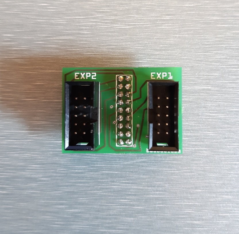
Here’s my pin mapping on the I/O module connector:
Smart Controller Exp2
Pin 1 MISO
Pin 2 SCK
Pin 3 PH1
Pin 4 SS
Pin 5 PH0
Pin 6 MOSI
Pin 7 PA3 (SD Detect)
Pin 8 RST
Pin 9 Not Used
Pin 10 Not Used
Next, go to ‘pins.h:350’ and change SDSS to “53.” This should be under the “#if MOTHERBOARD == 77” conditional. Then assign PA3 to the SD card detect pin by changing the “-1” to “25” on ‘pins.h:447.’
Line 350: #define SDSS 53
Line 447: #define SDCARDDETECT 25 // Ramps does not use this port
No more initializing the SD card. Insert a properly formatted card and Marlin will let you see its files. Enjoy!
… and ask questions. I’m sure I missed something.
- Michael