K8055 Thermistor project

Hello,

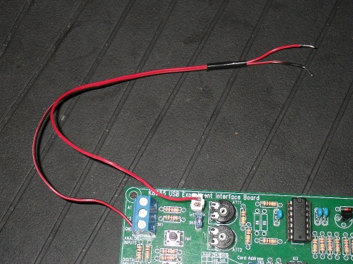
I’m working on a thermistor project for my K8055 board ( the project can be seen here stubbsnet.co.uk/projects/K80 … mistor.htm , ignore the top secret stamp, that’s just for fun)

I’m using a 150k Bead thermistor and a 150K resistor.

I notice the resistance on from the thermistor reads correctly when the interface card is not connected to the USB (at about 150Kohms), but as soon as the USB is connected the resistance seems to drop to about a 3rd of what it should be. Even when there is no power running being supplied to the thermistor.

I’m thinking it is to do with the circuit inside the K8055

Can anyone help??

Chris

Hi Chris,

I think that the 100 KOhms across RV1 need to be taken into account as part of your balance resistor. Since the two are in parallel, your balance resistor is only 60K, not 150K.

It may also help to use an OP-AMP in a way, that the input signal at A1 uses the full 0…5V range for the intended temperature range.

I don’t have a 150K thermistor at hand, only a 10K. But I also have an MCP6002 in my spare parts. If I find the time later today I can put that together and post the results here.

Regards,
Jan

Here we go.

First of all, I usually draw power from the K8055 like this:

The upper pins of SK1/SK2 are connected to the +5V USB supply voltage. So that there is a 5V power source for me without sacrificing an analog out port.

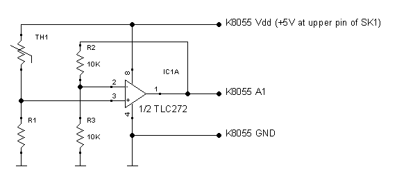
With that as Vdd power source, this is what I used for testing:

The TLC272 was the first OP-AMP I came across digging through my parts, so it was the one I used. Any similar OP-AMP should do in this case.

Let me try to explain that circuit. In my test setup, I used the 10K thermistor I had. A B57560G103F to be precise. According to the data sheet, it should have a resistance of about 33,000 Ohms around 0 degrees Celsius, 10,000 Ohms at 25 degrees and 3,600 Ohms around 50 degrees. Using my good old Casio TS-100 wrist watch/thermometer as a reference, test samples I took at room temperature, inside the fridge and inside the convection oven matched up quite nicely. Everything within +/- 2%. Can’t ask for anything better in a home setup like that.

So let’s try to create a setup that can measure 0…50 degrees Celsius (reasonable range for an average living room).

With R1 being 3K9 and Vdd assumed to be 5V, the voltage at input pin 3 of the OP-AMP is assumed to be between 2.6V (TH1=3600 Ohms at 50 degrees C) and 0.528V (TH1=33000 Ohms at 0 degrees C). R2 and R3 building an exact 2:1 voltage divider, the OP-AMP will (try to) maintain exactly twice the voltage of input pin 3 on output pin 1. Try to, because it obviously cannot produce 2x 2.6V = 5.2V.

So for practical purposes, I think this setup will be good enough for measuring anything between 10 and 40 degrees Celsius with reasonable accuracy. Getting 0…50 degrees would require to sacrifice some input accuracy by using 3K3 for R1.

Regards,
Jan

[quote=“MostlyHarmless”]Here we go.

First of all, I usually draw power from the K8055 like this:

The upper pins of SK1/SK2 are connected to the +5V USB supply voltage. So that there is a 5V power source for me without sacrificing an analog out port.
[/quote]

I like that, I thought of using a connection from A2 while the SK3 Jumper was connected, that gave me 4.95v, but I’ll have a go at the same as your way.

I’ve ordered the same op-amp from ebay as I don’t know anything about op-amps, I thought I would go with what is suggested. As I have a 10k thermistor and a strip of 10k resistors from ebay which I bought after I started the temperature projects. All I’m short of is the 3K9 Resistor for R1 and I should be able to put together your circuit…

Thanks for that, as soon as the op-amp comes I’ll give it a go…

It’s a shame it can’t be done without the op-amp, the Arduino seems to cope without it and I was hoping the K8055 would be the same, I like things simple…

you said earlier …

Could the same result be reached by altering the value of the balance resistor?

Taking temperatures seems a fundimental part of experimenting with I/O boards and I’ve seen a few posts about it, what I was aiming for when I started the project was to find the simplist way of doing it.

Thanks for youre halp I really appreciate it.

Chris

Note that the OP-AMP used on the K8055 itself is a TLC274. Sounds similar? Well, it’s the EXACT SAME thing. Only that the 274 has 4 individual (amplifier) circuits, while the 272 only has two of them. There is system to this madness. 274 = 4 OP-AMPs in one chip. 272 = 2 OP-AMPs in one chip.

Next time you order anything online, just add an E12 variety pack of resistors for good measure. It’s less than your average shipping cost and will have all the resistors you need for the next 2-5 years. Same with capacitors and electrolyte capacitors. You look like someone, not afraid of putting something together on a bread board just to see what it does, or if it does what you think it should do. You want to have that “bag of resistors”. Trust me.

[quote=“chrisstubbs67”]Thanks for that, as soon as the op-amp comes I’ll give it a go…

It’s a shame it can’t be done without the op-amp, the Arduino seems to cope without it and I was hoping the K8055 would be the same, I like things simple…[/quote]

There is a difference between the Arduino and the K8055. The Arduino exposes the raw PIC I/O ports to you while the K8055 has some protective circuitry around the microcontroller. In some cases this makes it easier to hook up an Arduino to sensors. In some cases it makes it easier to fry the Arduino for good.

[quote=“chrisstubbs67”]you said earlier …

Could the same result be reached by altering the value of the balance resistor?

Taking temperatures seems a fundimental part of experimenting with I/O boards and I’ve seen a few posts about it, what I was aiming for when I started the project was to find the simplist way of doing it.

Thanks for youre halp I really appreciate it.

Chris[/quote]

I hoped you’d notice this.

What do you think would happen if you simply connected your 150K thermistor between the +5V of SK1 and A1?

DO NOT TRY IT FIRST! For your own benefit, look at the schematics and try to answer the question “what should happen” before you wire it up and poke around with your DVM. Part of the answer is RV1.

Regards,
Jan

Hi

Yea… I got that when I was looking for one for the project

I’ve been thinking about that and will let you know as soon as I have a conclusion, FRi/Sat/Sun are my main work days so it may not be until Monday now…

But I have a question, how do you work out the value of the R1 resistor in your curcuit?

Chris

First I have to define what my desired temperature range is. In my example I defined my use case to be an indoor thermometer with a range of 0…50 degrees Celsius.

I then look at the data sheet for my thermistor, which is here: epcos.com/inf/50/db/ntc_09/G … _G1560.pdf . On page 9 we find a column for the temperature range 0…100, which tells us the resistance for 0.0 degrees = 3.3024 and for 50.0 degrees = 0.35828 (x 10K base resistance). In a resistor voltage divider like TH1, R1 in my example, the voltage at the point between TH1 and R1 is defined as

V = Vdd * (R1 / (R1 + TH1))

That voltage is the input of the OP-AMP at pin 3. If I make R1 equal to the lowest resistance I expect, then the highest voltage that can occur on that input is half the supply voltage or 2.5V. There is no 3K6 Ohm resistor in the E12 series, so I should use the next smaller one which is 3K3. With that, the voltage at 50.0 degrees should be 2.397V and at 0.0 degrees 0.454V.

Now comes the OP-AMP. What that thing tries to do is to keep pin 2 at the same voltage, pin 3 has, by changing its output voltage on pin 1. Since R2 and R3 build an exact 2:1 voltage divider, the OP-AMP needs to maintain twice the voltage of pin 3 to make that happen. This means that the output on pin 1 will have 0.908V at 0.0 degrees and 4.795V at 50.0 degrees Celsius. That is a range that will work very well with the K8055.

There are some not so obvious advantages of using an OP-AMP in this fashion. The thing has an extremely high input impedance of 10 to the 12th power Ohm (that’s a tera-Ohm or 1 million mega-Ohm). This is why its resistance in parallel to R1 can be ignored. It does not affect the voltage divider TH1/R1. The 100K input impedance of the K8055 does.

The other advantage is not relevant in the K8055 case, because the K8055 has another OP-AMP acting as a voltage follower in there. But it would be important in the Arduino case, where you connect stuff directly to the I/O ports of the microcontroller. The A/D converter works by charging a capacitor from the input pin, then disconnecting it from the input and discharging it over a known resistance. The time it takes to discharge lets the microcontroller know what its initial charge voltage was. This means that the microcontroller will connect a capacitive load in tiny bursts and that can affect the reading! The OP-AMP acts as a buffer between the sensor and the microcontroller. The load at the output does not affect the OP-AMPs input.

Regards

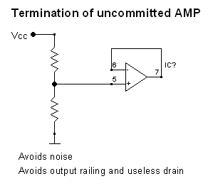
One more detail. The schematics I posted is incomplete.

The TLC272 is a dual OP-AMP, so in this case it is only half used. You can either use a TLC271 instead, or you should properly terminate the unused half like this:

[quote=“MostlyHarmless”]

I hoped you’d notice this.

What do you think would happen if you simply connected your 150K thermistor between the +5V of SK1 and A1?

DO NOT TRY IT FIRST! For your own benefit, look at the schematics and try to answer the question “what should happen” before you wire it up and poke around with your DVM. Part of the answer is RV1.

Regards,
Jan[/quote]

Either
In the first few miliseconds the voltage will be amplified to something silly… followed by a small fire
or
Nothing bad will happen, there is no gain resistor on my board (I.e. nothing in R8 or R9 ) on my k8055 board, so from what I have read on the internet about op-amp circuits… so the output will be just below the input

I think the first option…?

I’m also thinking I should invest in some software to try out the circuits before I build them…And I’m still waiting for my opamp and bits… I hope they come soon…

By the way if you take out the thermistor and replace it with some electrodes (bare wires) would it make something to measure the skin resistance… i.e. A lie detector? (Ok I’m 44 and still a big kid) or would it be a quick way of getting an electric shock?

Chris

[quote=“chrisstubbs67”]Either
In the first few miliseconds the voltage will be amplified to something silly… followed by a small fire
or
Nothing bad will happen, there is no gain resistor on my board (I.e. nothing in R8 or R9 ) on my k8055 board, so from what I have read on the internet about op-amp circuits… so the output will be just below the input[/quote]

An amplifier cannot output more than its supply voltage, which is +5V in this case. If the input voltage (pin 2) times the gain factor exceeds the supply voltage, the amp will “clip”. You can simulate and listen to the result in any good audio editor.

But let’s see how that thermistor would look like in a schematic drawing. Here is the relevant portion of the K8055 schematic with the thermistor connected:
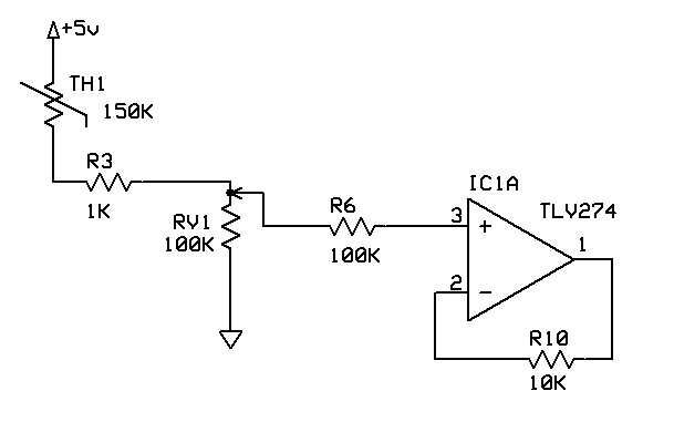
I have drawn RV1 a little “wrong” to illustrate this, because that is how it is actually configured when you have jumper SK2 removed and the potentiometer turned all the way clockwise, which you normally have to measure something on A1.

At 25 degrees, the thermistor TH1 has 150K Ohm resistance. R3 is in series with it, so the two together have 151K. The potentiometer RV1 is between the two main terminals just a simple 100K resistor. And since it is turned fully clockwise, the wiper actually directly connected to R3 without any resistance in between any more. b and RV1 build a classic voltage divider![/b] With +5V going into TH1, the voltage at the wiper, which is the point where R6 connects, is

V = Vdd * RV1 / (TH1 + R3 + RV1)

V = 5 * 100K / (150K + 1K + 100K) = 1.99V

Measure it. If you don’t have one, a good digital multi-meter that can measure Volt, Ampere and Ohms is IMHO a must have for this hobby.

Now those 1.99V go into R6, which is just a current limiter that doesn’t change the voltage. Without R8 the OP-AMP is configured as a voltage follower, so the same voltage that you measured at the middle connector of RV1 will be on pins 2 (input) and 1 (output) of IC1. Pin 1 then also goes directly into the A/D converter. The voltage will rise when it gets warmer as the thermistor will have less resistance, and it will get lower the other way around. Depending on your intended temperature range, this configuration may not use a lot of the available voltage range, but whatever happens, the input voltage into the OP-AMP can never exceed the 0…4.95V range. The measurement may be a little coarse, but this is a working thermometer.

[quote]I’m also thinking I should invest in some software to try out the circuits before I build them…And I’m still waiting for my opamp and bits… I hope they come soon…

By the way if you take out the thermistor and replace it with some electrodes (bare wires) would it make something to measure the skin resistance… i.e. A lie detector? (Ok I’m 44 and still a big kid) or would it be a quick way of getting an electric shock?

Chris[/quote]

I don’t have any simulation software. I just use ExpressSCH to draw the circuit and then try it out. At 47 I still love the try and error method. I think I was 16 when I had the last capacitor exploding, so I trust my math by now.

You won’t get an electric shock from 5V. Skin resistance is somewhere in the mega Ohms. Same circuit, different resistor.

BTW, there is a reason I had that 10K thermistor laying around. It was in the same box as the humidity sensor and the pressure sensor. Get the idea? Measuring humidity will be fun, but requires one more feature in the K8055 Open Source firmware (for the PIC18F). The sensor I have is a Humirel HS1101, which is a variable capacitor that has 173pF at 30%, 180pF at 55% and 191pF at 80% RH. That can be used with a 555 timer to convert relative humidity into a frequency. I already had a bread board setup that produced frequencies around 1400 Hz. Something the PIC18F I am using could easily count on a digital input port. I have not played with the pressure sensor yet.

Regards
Jan
Thank you so very much for your help…

My Op-amp came yesterday and I made up the circuit… However it was still calculating everything wrong.

It was reading the right voltage into the interface according to my multimeter, but when it did the calculations to turn that into resistance it was way out… I got tired and thought of doing sometrhing else so I took the 3k9 resistor and used that in my original simple voltage divider. Altered the value in my software and low and behold it came up with exactly the right room temperature when I ran my program. So I’m going to test that at different temperatures and see how well it works… More news as it happens…

But a big thank you for your help…

The project can be seen at stubbsnet.co.uk/projects/K80 … mistor.htm

Chris

The op-amp in my circuit simply duplicates the voltage, that it gets from the thermistor/3K9 voltage divider. According to the datasheet of “my” thermistor, for the temperature range of 0-100 C it has a beta value of 3450. The resistance at 0 C should be 27936 Ohm and at 50 C 4103 Ohm.

Using a 3K9 resistor and assuming 5V supply it should have a voltage of 0.61V at 0 and 2.44V at 50. The op-amp multiplies that by 2, so the value read by the ADC should be in the range of 62 to 250.

If you connect that voltage divider directly to the K8055, then you need to take the 100K resistor RV1 (ATT1) into account. It is in parallel to your resistor, which changes the resistance from 3900 to 3754 Ohm. The resulting voltages now are 0.59V at 0 C and 2.39V at 50 C. That would result in an ADC range of 30 to 122.

I did notice the temperature reading was about double, but when I halved the final temperature I got 27C instead of 22C which would have been correct. It looked like the resistance was being miscalculated. I still have your circuit wired up on one (plug)board? and I have the divider on another one, I’ll see what I can do with them on monday when I get some freetime again. I guess I was so hopeful waiting for my last couple of bits to arrive, the op-amp especialy, when it didn’t work straight away I was a but put off…

Chris

Hi,

[quote=“MostlyHarmless”]

If you connect that voltage divider directly to the K8055, then you need to take the 100K resistor RV1 (ATT1) into account. It is in parallel to your resistor[/quote]
ATT1 is turned fully clockwise, shouldn’t there be no resistance from it??

In my room which according to an independant thermometer is 22DegC… The op-amp circuit gives the following values

Analogue value on A1 (well actualy I’m using A2 now) = 133
Voltage = 2.5716796875
Resistance = 3606.7669172932330827067669173
Temperature = 49.7

Using the same maths, the voltage divider with a 10k balance resistor gives

Analogue value on A1 = 114
Voltage = 2.204296875
Resistance = 12456.140350877192982456140351
Temperature = 20.2

Using the same maths, the voltage divider with a 3.9k balance resistor gives

Analogue value on A1 = 64
Voltage = 1.2375
Resistance = 11700
Temperature = 21.5

it is still 22C in here

It looks like thew opamp doubles the voltage and adds and a little extra to the value…??

Chris

BTW. my thermistor is :-
NTCL Series NTC 10 kOhm ± 0.75 % 3977 Radial Thermistor

Pièce Fabricant: 2381-640-63103

Type de montage: Through Hole
Modèle de paquet: RADIAL
Emballage: BOX
Quantité d’emballage normalisé: 500

ATT1 has 3 terminals. One connected to R3, one (the wiper) going to pin 3 of IC1A and the third one to ground. ATT1 fully clockwise means no resistance between the wiper and R3, but RV1 is still a 100K resistor to ground.

Because the op-amp is doubling the voltage. You need to divide the measured voltage from the op-amp’s output before you try to calculate the resistance. Your input voltage 2.57 V means a 11275 Ohm thermistor resistance.

I created the whole test setup again and discovered something I hadn’t expected. My USB port supplies 5.1 V and at 25 degrees the thermistor plus the 3K9 resistor (nothing else connected) should mean 0.367 mA current. But I measured between 0.38 and 0.39 mA. That means that the resistance of the thermistor is only around 9350 Ohm now. When measuring the thermistor alone, it is dead on 10K. The voltage over that thermistor is 3.6 V and with that current, it consumes almost 1.3 milli W power. Apparently enough to warm up its inside by 2 degrees.

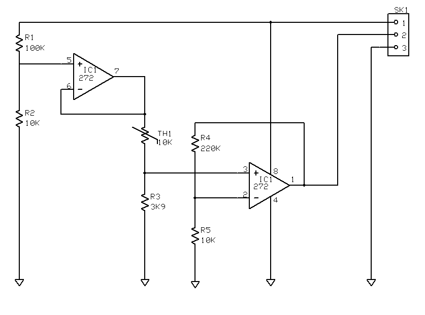
Here is what I did next:

The voltage divider R1,R2 has a factor of 11 which brings down the 5.1 V supply to 0.464 V. The op-amp pins 5-7 are a voltage follower so that the remaining circuit, especially the thermistor, can’t affect that voltage.

That 0.464 V is now what goes through the thermistor and R3. Same 13900 Ohm total resistance, but because of the much lower voltage, the power consumption of the thermistor is only 10.7 micro W, which is about 1/120th of what it had before.

The result should be 0.130 V on pin 3 of the second op-amp. The voltage divider R4,R5 makes the op-amp amplify this by factor 23, which results in 2.99 V on pin 1.

Calculating the thermistors resistance from that is still rather simple. TH1 = Vdd / (V / 23 * 11) * R3 - R3. With Vdd=5.1 and V=2.99 I get 10009 Ohm.

Those are theoretical values. In reality the output I have is 2.96 V which my PIC18F2550 converted K8055 reads as 2.95 V. All the resistors in the entire setup are up to 2% off, so I consider that within the tolerances.

That worked, it’s now saying it’s a 22C and the room IS 22C

I’ve not had time to do the rest of the circuit, might have a go on monday…

Are you getting your power from SK1 now or should that be the powered side of the SK2 jumper??

Chris

That worked, it’s now saying it’s a 22C and the room IS 22C

I’ve not had time to do the rest of the circuit, might have a go on monday…

Are you getting your power from SK1 now or should that be the powered side of the SK2 jumper??

Chris[/quote]
Great.

SK1/SK2 doesn’t matter. They both connect to the USB supply voltage.

Hi,

I don’t have the parts for the latest circuit yet so I thought I would test the old one with the voltage halved as you suggested. As I said earlier my room was at 22C so I took the K8055 and the plugboard with the opamp circuit and placed them into a coolbox with some freshly frozen icepacks and two independent thermometers (one digital and one conventional liquid in a glass tube type) and from 22C down to 8C the final reading from the circuit matched the actual temperature well with it being no more than I would say half a degree difference at any one time, but you have to remember the thermistor isn’e exactly where the thermometer is, only as close to it as I could get. I have worked as an auditor in the food industry and the temperature probes we used there have a tollerance of ±1 degree so for me the origional opamp circuit is working fine.

I should get the rest of the parts on monday, so before then I’ll be trying to cool the thermistor as much as possible and likewise turn the heater on in this room so that I can check the readings with the actual temperatures…

Chris

By that I don’t mean it was out when it was less than 8, I mean 8 was the coldest the coolbox reached…

Just thought I would point that out

C

The circuit will work with other resistor combinations. Of course the voltage divider value and thereby attenuation/amplification factors will differ. You can use a 1K,10K combination to control an op-amp for a factor of 11 for example. It will use a little more current than is needed, but it’s not like 1/2 mA is going to cause any issues.

BTW, I have assembled a 10K thermistor into an old ball point pen housing like this:


The ends of that red shrinking tube are sealed with hot glue, so the whole thing is actually submersible. The holes are just for air/liquid circulation so that the pen interior follows temperature changes faster.

This assembly doesn’t withstand much above 50 Celsius (the hot glue will melt), but it protects the thermistor nicely and I don’t have to put the whole test board into the fridge/oven.

Jan