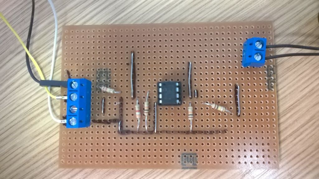
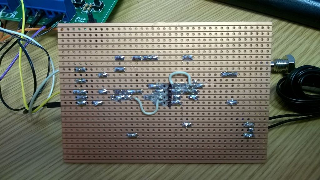
This thread is just about finished and I have 2 working thermistor circuits so I thought I would sum up.
I hope this thread helps anyone trying something similar, so …
In conclusion…
- Mostlyharmless is a very helpful person, and I would buy them a drink if they were here.
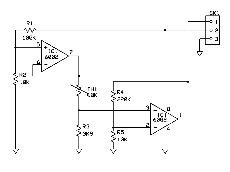
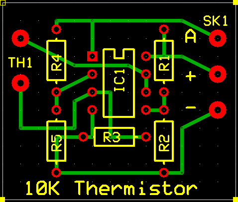
- Temperature can be captured with either a simple Voltage divider or using an opamp
- A temperature reading at normal temperatures certainly works, I have been able to test the circuits from 8degC up to 28DegC and both circuits work fine, and certainly within ±1degC.
Voltage divider v Op amp circuit
The voltage divider is a simple circuit, but you do have to take into account ATT1 (or att2 depending on which analogue input you are using), which gives 100kOhms to ground even when turned to fully open (no resistance). This means that in your calculations the resistance of the balance resistor becomes :-
Total balance resistor Resistance ® = 1/((1/your actual balance resistor)+(1/100))
So for a 3k9Ohm balance resistor
R= 1/((1/3.9)+(1/100))
Which is
R=1/(0.25641+0.01)
Or
R=1/0.26641
Which equals
3.75360924 kOhms Or 3753.60924Ohms
In the software we use the values in Ohms rather than kOhms but the effect is the same
[b]Dim decBalanceResistorOhms As Integer = 1 / ((1 / 3900) + (1 / 100000))[/b]
If you use the op-amp circuit you don’t need to work this out at all. The op-amp circuit doubles the voltage which reaches the analogue input so more of the 0-255 range of the input is used and although value for the voltage then needs to be halved for the maths to work, the result is a better scale. For example, the voltage divider steps from 23.3C to 23.7 but the op-amp circuit goes 23.3 to 23.5 to 23.7.
Doing the maths…
You need the following values to do the maths.
• The supply voltage, I have powered this project from the positive side of the SK2 or SK3 jumpers. By taking the jumper off then reattaching it over just the powered pin you can use it as a plug by attaching a wire to it (there is a picture of this on the website) for me this is 4.95v but it is whatever the USB supply voltage is.
• The value of the balance resistor, for the op-amp circuit this is the R1 Value and for the Voltage divider you have to work it out taking into account of ATT1 (or ATT2, see above)
• The beta value for your thermistor, which can be found on the datasheet for the thermistor which you can usually get from the supplier’s website
• R infinity for your thermistor which is calculated by
((Resistance in ohms at 25 Deg C) * (e^((minus (the beta value for the thermistor))/ (25 Deg C as Kelvin))
For this project this was
Rinfinit = 10000 * (e^((-3977) / 298.15)) =0.0161056846
First calculate the voltage in at the A1 or A2 pin (these examples are in VB, I use very descriptive variables hope you can understand them)
Dim intValueOfA1 As Integer = ReadAnalogChannel(1)
Dim decVoltageAtA1 As Decimal = (decVoltageSupply * (intValueOfA1)) / 256
If you are using the op-amp circuit then this must be halved so that line becomes :-
Dim decVoltageAtA1 As Decimal = ((decVoltageSupply * (intValueOfA1)) / 256) / 2
Then you can calculate resistance of your thermistor
Dim decResistance As Decimal = (decVoltageSupply * decBalanceResistorOhms) / decVoltageAtA1 - decBalanceResistorOhms
Now that you have a value for your thermistor you can calculate the temperature (in Kelvin)
Dim decTempKelvin As Decimal = intThermistorBetaValue / (System.Math.Log(decResistance / decRinfinit))
To get Celsius you can then
Dim decTempCelsius As Decimal = Math.Round(decTempKelvin - 273.15, 1)
Which will give you deg C to one decimal place.
so it all looks like [quote]
Public Class Form1
Public Declare Function OpenDevice Lib “k8055d.dll” (ByVal CardAddress As Integer) As Integer
Public Declare Sub CloseDevice Lib “k8055d.dll” ()
public Declare Function ReadAnalogChannel Lib “k8055d.dll” (ByVal Channel As Integer) As Integer
Const decRinfinit As Decimal = 0.0161056846
Const decVoltageSupply As Decimal = 4.95
Const intThermistorBetaValue As Integer = 3977 'The beta value of the thermistor
'TIMER 1 IS THE ROUTINE YOU WOULD USE FOR A VOLTAGE DEVIDER CIRCUIT
Private Sub Timer1_Tick(sender As System.Object, e As System.EventArgs) Handles Timer1.Tick
    Dim decBalanceResistorOhms As Integer = 1 / ((1 / 3900) + (1 / 100000)) 'the ohms of the balance resisitor for the voltage divider
    'Read the analog port 0 and convert the value to volts.
    Dim intValueOfA1 As Integer = ReadAnalogChannel(1)
    Dim decVoltageAtA1 As Decimal = (decVoltageSupply * (intValueOfA1)) / 256


    'Calculate the Resistance
    Dim decResistance As Decimal = (decVoltageSupply * decBalanceResistorOhms) / decVoltageAtA1 - decBalanceResistorOhms
    'the next line calculates the temp in Kelvin
    Dim decTempKelvin As Decimal = intThermistorBetaValue / (System.Math.Log(decResistance / decRinfinit))


    'Display temp on Form
    tbxDigitalValue1.Text = intValueOfA1
    tbxVoltage1.Text = decVoltageAtA1
    tbxResistance1.Text = decResistance
    tbxC1.Text = Math.Round(decTempKelvin - 273.15, 1)

End Sub
'TIMER 2 IS THE ROUTINE YOU WOULD USE IF YOUR CIRCUIT WAS USING AN OPAMP
Private Sub Timer2_Tick(sender As System.Object, e As System.EventArgs) Handles Timer2.Tick
    Dim intBalanceResistorOhms As Integer = 3900
    'Read the analog port 0 and convert the value to volts.
    Dim intValueOfA2 As Integer = ReadAnalogChannel(2)
    Dim decVoltageAtA2 As Decimal = ((decVoltageSupply * (intValueOfA2)) / 256) / 2


    'Calculate the Resistance
    'Dim r1a As Decimal = (decVoltageSupply * intBalanceResistorOhms) / decVoltageAtA2
    Dim decResistance As Decimal = (decVoltageSupply * intBalanceResistorOhms) / decVoltageAtA2 - intBalanceResistorOhms
    'the next line calculates the temp in Kelvin
    Dim decTempKelvin As Decimal = intThermistorBetaValue / (System.Math.Log(decResistance / decRinfinit))


    'Display temp on Form
    tbxDigitalValue2.Text = intValueOfA2
    tbxVoltage2.Text = decVoltageAtA2
    tbxResistance2.Text = decResistance
    tbxC2.Text = Math.Round(decTempKelvin - 273.15, 1)

End Sub


Private Sub Form1_Load(sender As System.Object, e As System.EventArgs) Handles MyBase.Load
    OpenDevice(0)
End Sub

Private Sub Form1_FormClosing(sender As Object, e As System.Windows.Forms.FormClosingEventArgs) Handles Me.FormClosing
    CloseDevice()
End Sub
End Class[/quote]
And that should be all…
Thank you for all the help…
Chris
