EDu09 does not work

After connection of assembled edu09 module, message "no hardware response appears. Red LED is on.

Checked all solder connections, can’t see a problem.

Are there any measurements I can check?

Could send fotos, but do not know, how?

Many thanks for your help,

Karl Sruc karl.sruc@aon.at

You can just drag and drop pictures in the reply box :slight_smile:

Those should be the fotos. I had to replace the 16 pin IC Socket by two 8 pin which I had at hoem, as the one delivered was defective (see Foto).

Your help is highly appreciated

The pictures look OK.

Do there appear two new devices under the ‘Human Interface Devices’ in the Device Manager when the the EDU09 is connected to the PC?

edu09_hid

If they do not appear, check the voltage on pin 20 of IC3.
The voltage should be 3.3V

Don’t think so. This how the “Gerätemanger” looks, before an after connecting EDU09 - no change:

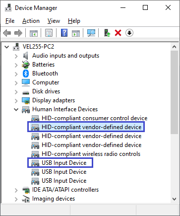
It seems there is no USB communication between EDU09 and PC.
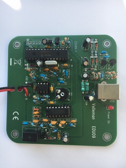
Did you check the voltage on pin 20 of IC3?
If voltage OK, please try other USB cable if possible.

Which one is pin 20? How do they count? Which voltage is expected there?

OK, guess I found it: Left from the notch is pin 1, then counts counterclockwise, right? So right side from bottom starts with 15, then up 16… 20 measures -3,36 V.

Tried four different USB Cables - no effect. 5 V enters the board from the USB Plug.

You are right how to count the pins.
(The voltage on this pin should be positive compared to GND.)
Anyhow, the voltage value 3,36 looks OK.

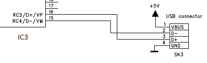
Please check the connection between IC3 and USB connector:
Check that there is connection between the USB connector pins 2 and 3 and pins 15 and 16 of IC3.
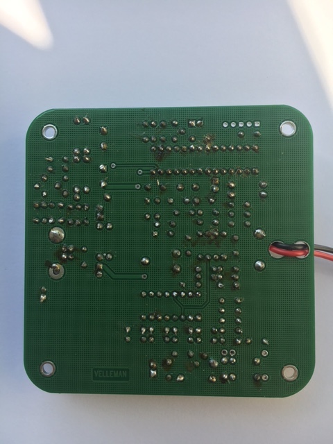
Check also that there is no short circuit to GND and no short circuit between the pins 15 and 16.

edu09_usb

No short between 15 and 16.

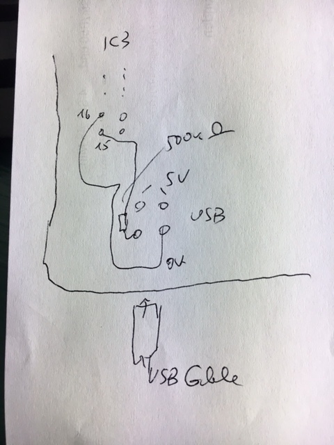
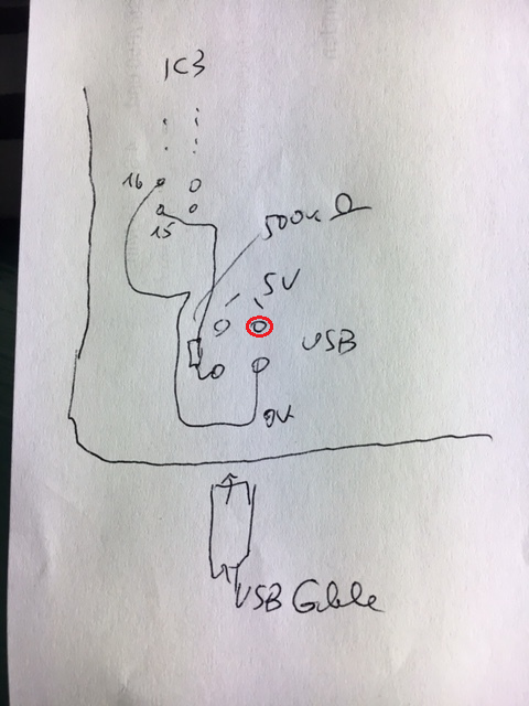
Don’t know the numbering of the USB Plug, however, see drawing:

The two upper (inside the board) Pins have 5V between them. From the lower / outer Pins, the Right one connects to 16, the left one measures 500 kOhms to pin 15. Resoldering did not help.

The upper right pin should be connected to pin 15.

“Upper” means next to the edge of the board, the pin were I currently measure 500k ohms to pin 15? I simply bridge that?

No - I meant the upper right in your drawing.
Marked with red circle in this picture:

This pin should be connected to pin 15.
Please check…

Oh, I see.

Will be out of home for a week, try after return.

Connection from red dot to pin 15 on IC3 is ok

The next test:
Please check the voltage on pins 9 and 10 of IC3.
There should be about following voltages:
0.8V on pin 9
1.5V on pin 10

These are the pins connected to the crystal X1.

Result: 9 =0,9V 10=1,56 V…………

Seems to be OK too.
Strange problem indeed…
You can return the EDU09 for inspection/repair to your local Velleman dealer or direct to:

Velleman Projects Tech. Dept.
Legen Heirweg 33
9890 Gavere
Belgium