I have just bought EDU09 and tried to assembled it.
Of course, as I am very new in electronic and solder actions this has not been so simple but the only real issue I encountered has been when I mounted R18 resistor in place of R28! When I unmounted R18 I broke it and replaced it with 2 resistors I had (in serial to obtain the same resistor value, I checked and it was apparently OK)
At the end, I plugged EDU09 to my PC and was happy to see the calibration OK (even if the led didn’t “light”)!
I tried then the advanced calibration as given by guide page 12 and then I saw strange and unstable values. I had a look on this forum and saw a post which said that it was due to bad “solder”. I check mines and saw that some of them was not very stable. So I re-soldered them and then problem occurs.
When I retried and obtained the following result:
The led did some light during a short time and the calibration result was:
Soldering with ICs mounted should not be a problem.
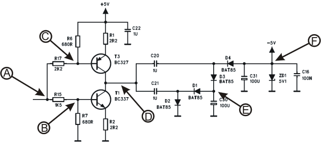
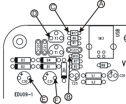
As a first test you may check the voltage on pin 1 of IC2.
When the USB cable is plugged in there should be about 1.5V.
When the EDU09 program is running, there should be 1.65V.
Well, I suppose that the pin1 is at the level of the black dot on IC2 right?
If yes:
When the USB cable is plugged in = -0.56
When the EDU09 program is running = 2.47
Note that it is possible that I damaged the PCB when I unmounted the R18 resistor I had put wrongly in place of R28… could bad contact on R28 could be the reason?
Hello,
First of all, thanks for your efficient support.
Secondly I tried to measure as requested. The problem is that some values change during measurement! But I think that the biggest problem is that I never find same values than you.
Here are the voltages measured on IC2 pins when USB cable plugged in:
1: 1.53V ==> 0.86
2: 0V ==>0.30
3: 0V ==> 0.16
4: -5.2V ==> 0.48
5: 0V ==> 0.08
6: 0V ==> 2.20
7: -1.69V ==> 0.45
8: 5.0V ==> 1.81
Here are the voltages when the software EDU09 is running:
1: 1.63V ==> 0.69
2: 0V ==> 0.77
3: 0V ==> 0.32
4: -5.2V ==> 0.69
5: 0V ==> 0.26
6: 0V ==> 3.26
7: -1.69V ==> 0.69
8: 5.0V ==> 2.58
As you can see value as all differents! So the big question is: may be it would be better to re-buy another kit and to re-build from scratch (as said I am a beginner with the classical error cycle : error <=> success )
The results are very strange.
For example on pin 8 there should be voltage +5V, which is coming directly via L1 from the USB socket.
If L1 is properly soldered and not broken, there should be +5V on pin 8.
Please make sure you have a good ground reference for the DVM when doing the measurements.
You can use the USB socket’s “shield” as the ground reference.
Please make sure the shield is properly soldered to the ground plane of the board.
If there is still no +5V on pin 8, you can check if there is +5V on the wires of L1.
[quote=“Meziane”]The led did some light during a short time [/quote]This is also very strange.
The LED is connected via R8 to USB socket’s +5V. The LED should lit immediately when the USB cable is plugged in.
Please check the USB connector soldering.
The issue with the led seems solved. The solder of 1 usb pin was not to good. I fixed it and I also saw that my USB plug was not 100% compliant with the socket. Thus I tried several deep to plug it and I have found that I needed to plug it only at 85% deep (sorry but as Engligh is not my native language, some terms are missing from my vocabulary!).
I retried a calibration and obtained the following results:
[quote=“Meziane”]I checked L1 and L2 (there are chokes right?) and results are:
L1: 1.47
L2: 5.07[/quote]This seems to indicate that the +5V from the USB is properly coming to L2 but not to L1.
So also the whole input section (IC1, IC2) is not getting the +5V supply.
Please check why there is no +5V on L1.
The +5V should appear on both ends of the L1.
Also it seems that the charge pump is not working.
There doesn’t seem to be -5.2V on pin 4 of IC2 as should be.
During the calibration there must have been -5.2V on this pin.
If no -5.2V, the calibration should fail different way.
Here are the calibration results if charge pump is not working:
As you can see it is always the same. I am going to re-chek soldering points and also the charge pump voltages. Thanks for the diagrams. I’ll keep you updated… but I think not before several days.
I reviewed al soldered points and fixed several. Now I am happy to say that calibration is completed successfully and that measured voltages are compliant with those you mentioned. So a big thanks to you!
I tried also the advanced calibration as said into the guide page 12. Unfortunately I did’nt succeed.
When I launch the advanced calibration (DC mean) without plug the external battery, I have between -0.81V and 0.81V depending on RVI trimmer position.
When I connect the battery, I obtain the same values. Thus I suppose that it remains something wrong with my build. Could you say me how I could identify where is the problem (I’d like to avoid to have a regression and I’d like to modify only what is needed).
[quote=“Meziane”]When I launch the advanced calibration (DC mean) without plug the external battery, I have between -0.81V and 0.81V depending on RVI trimmer position.[/quote]This is normal result when the RV1 is adjusted.
[quote=“Meziane”]When I connect the battery, I obtain the same values.[/quote]This indicates broken connection in the input section.
Please make sure Coupling DC is selected (I think it is OK. This is the default setting when the software is run.)
[quote=“Meziane”]Note that it is possible that I damaged the PCB when I unmounted the R18 resistor I had put wrongly in place of R28… could bad contact on R28 could be the reason?[/quote]This can be the cause of the problem.
You can check the continuity by following way:
Disconnect the USB cable.
Measure resistance between the input clamp (Red) and IC1 pin 1.
There should be 75k ohm resistance between these points.
If not, check R28 connection.
If OK, check the input cable (red) connection.
If OK, heck the Ground input cable (black) connection.
When you get the input section working, you can do the advanced calibration.
Here are more detailed instructions how to proceed:
• In the ‘Options’-menu select “Expert Settings”.
• In the ‘View’-menu select “Waveform Parameters…”.
• In the ‘Waveform Parameters’-window select the check box “DC Mean”.
• Adjust RV1 to its middle position
Connect the input cables red and black together.
Select Options -> calibrate
Measure the output of the battery with a multimeter and remember it.
Connect the battery to the oscilloscope’s input.
Set Volts/Div. to “0.5V” and click the “Run”
button.
Adjust trimmer RV1 until the displayed “DC
Mean” value in the ‘Waveform Parameters’-
window corresponds with the measured value.
Remove battery.
If you had to adjust RV1 a lot, repeat the steps 1 to 7.
Well the cause is R28. As said at the beggining of my post, I initially did a mistake and wrongly soldered R18 at the R28 place. I unsoldered R18 and soldered R28 but I think that I damaged the PCB at the R28 place. Any means to workaround this?
[quote=“Meziane”]I unsoldered R18 and soldered R28 but I think that I damaged the PCB at the R28 place. Any means to workaround this?[/quote]You may try to locate the trace break and fix it.
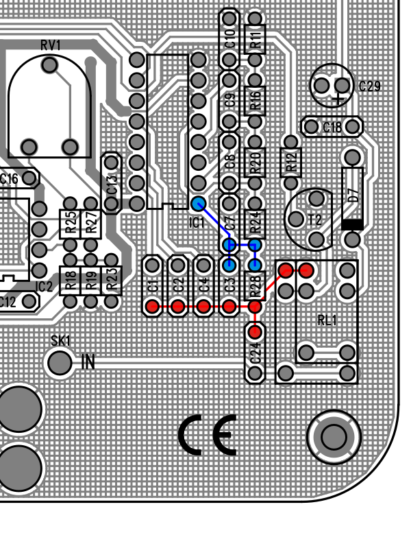
In this picture is shown a section of the PCB.
Please check that all the red points are connected together and also all the blue points are connected together.
If you locate disconnected points, you can solder a copper wire between them on the bottom side of the board.
Be careful not to make short circuit to the ground plane.
Thanks a lot for the pcb picture. This helped me a lot. I succeeded to wire between points (In fact it was only around R28)…
After I did a standard calibration and it has been completed successfully (you can imagine that I was a lot happy). I tried then the advanced calibration but has difficulties to adjust with VR1. I did several time and at a moment I decided to reinitialize EDU09 and to do again a standard calibration and this time it failed.
I measured then voltage on IC2 pins and now I have 3.44V on pin 1 (all others pin are OK). I tried to check again solderes points but find nothing. What could I check to solve this last issue (I hope that this will be the last)