I would like to share some information I think may be useful for some of you.
Over 2 years now, I been trying various modifications in order to improve the print quality of the K8200 printer.
One of the many things I tried was to swap the original A4988 stepper drivers with the 32-microstep capable stepper drivers
named DRV8825. I soon discovered that my stepper motors was not running smoothly and that the driver boards was skipping
microsteps on a regular basis, even at very slow speeds (try “G91”, then “G1 F20 X10” and you will hear it).
Changing the reference voltage did not help.
Id did, and the result is a much smoother print and reduced printer noise.
It seems that not many are aware of this patch.
With this fix I think my K8200 printer is now performing really well.
Just to summarize, I have made the following changes:
Upgraded standard M8 Z-leadscrew to K8204, (good quality improvement)
Upgraded to GT2 belts and pulleys, (not a big quality difference)
Upgraded to the 0.35mm direct drive extruder K8203, (not working well for me)
Rebuilt the extruder, It is now a mix of the original geared extruder + hotend from K8203 (good quality improvement)
Replaced the A4988 driver boards with DRV8825 driver boards + diode patch (good quality improvement)
Hope this information is useful for someone.
Comments are welcome.
These are some great articles. Thank you for posting them!
I have been using 8825’s at 1/32nd microstepping to drive my X and Y axis motors, and had not noticed any non-linearity. But I also have not made any attempt to measure it. I will try your g-code experiment next time I am at the printer.
I also use 0.9-degree steppers instead of 1.8-degree, which does cause a noticeable improvement in printer resolution. I suspect (but haven’t measured) the current used in these motors will be lower, since they are only doing half of the work-per-step. (EDIT: This is wrong since the stepper coils will be holding at constant current.) But the article implies that low current is where the problems lie, so I might even be making the 8825 problem worse.
I wonder if this might also help to explain the clicking sound some of us have experienced with the K8203 extruder, which uses the 8825 to drive the extruder motor.
It should be easy to make a short cable adapter to insert the four diodes inline with each motor, then I can A/B test the results. This mod will increase the current being drawn from the stepper drivers, so I expect them to get a bit hotter with these installed.
Thanks again for the links. Great information about stepper drivers and micro-stepping there!
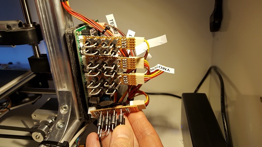
Dr. Vegetable, here is a picture of my diode patch:
I admit it doesn’t look very pretty…
The diodes get a bit hot, so I arranged them with some spacing between them.
The current drawn from each stepper driver will be the same as before, but the voltage drop
over them will be reduced by 1.4 volts because of the voltage drop over the diodes.
In theory this means that the drivers should generate less heat than before (I havent
verified this though).
I have replicated your results. When I execute your g-code I can hear the motor moving in short bursts. I then added the diode circuit and the motor movement sounds much more even to the ear.
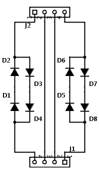
I modified the circuit slightly to make it easier to build. Instead of putting all four diodes on a single motor lead, I put two diodes on each motor lead. All four diodes are still in series with the motor coil, but there are two coming, two going. I used 1N5408’s (the only part I could easily source) and so the leads were a bit heavy gauge. They fit into this Radio Shack proto-board:
I haven’t looked at the signals on a scope, but it seems like this does make a difference. I’ll wire up the other motors and take it for a test print…
Did you get a noticeable improvement in print quality when you did this?
So I made three copies of this circuit and mounted them on my X and Y axes (both upgraded with DRV8825s) and also one for my extruder, which is a K8203 running off a DRV8825. I did not bother to do any of this for my Z axis, which is running on the stock A4988.
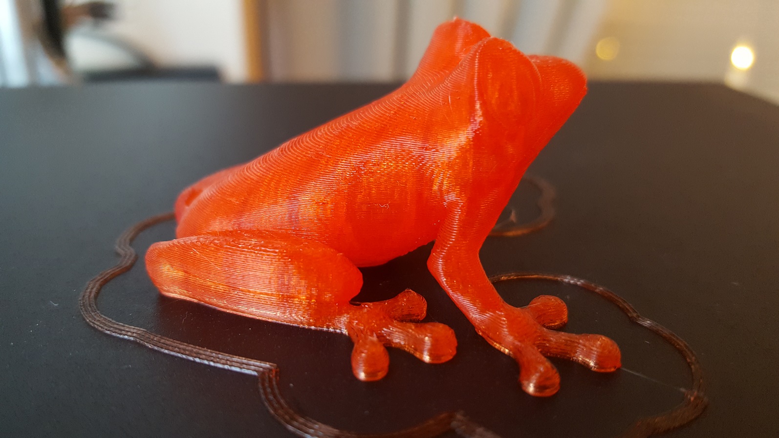
It is difficult to tell, but I think the test print is clearer. The ridges across the back of the Tree Frog are very even. I think this may have smoothed out the slight variations in material flow that I had been seeing before. Some details around the edges of the mouth and eyeballs are clearer on this print than I remember seeing before.
The printer also seemed to shake less during hex fills, and is as quiet as it has ever been. The diodes get warm during print jobs, but not so hot that I cannot touch them.
Time will tell if this modification is worth the cost of all those diodes, but it doesn’t seem to have hurt anything.
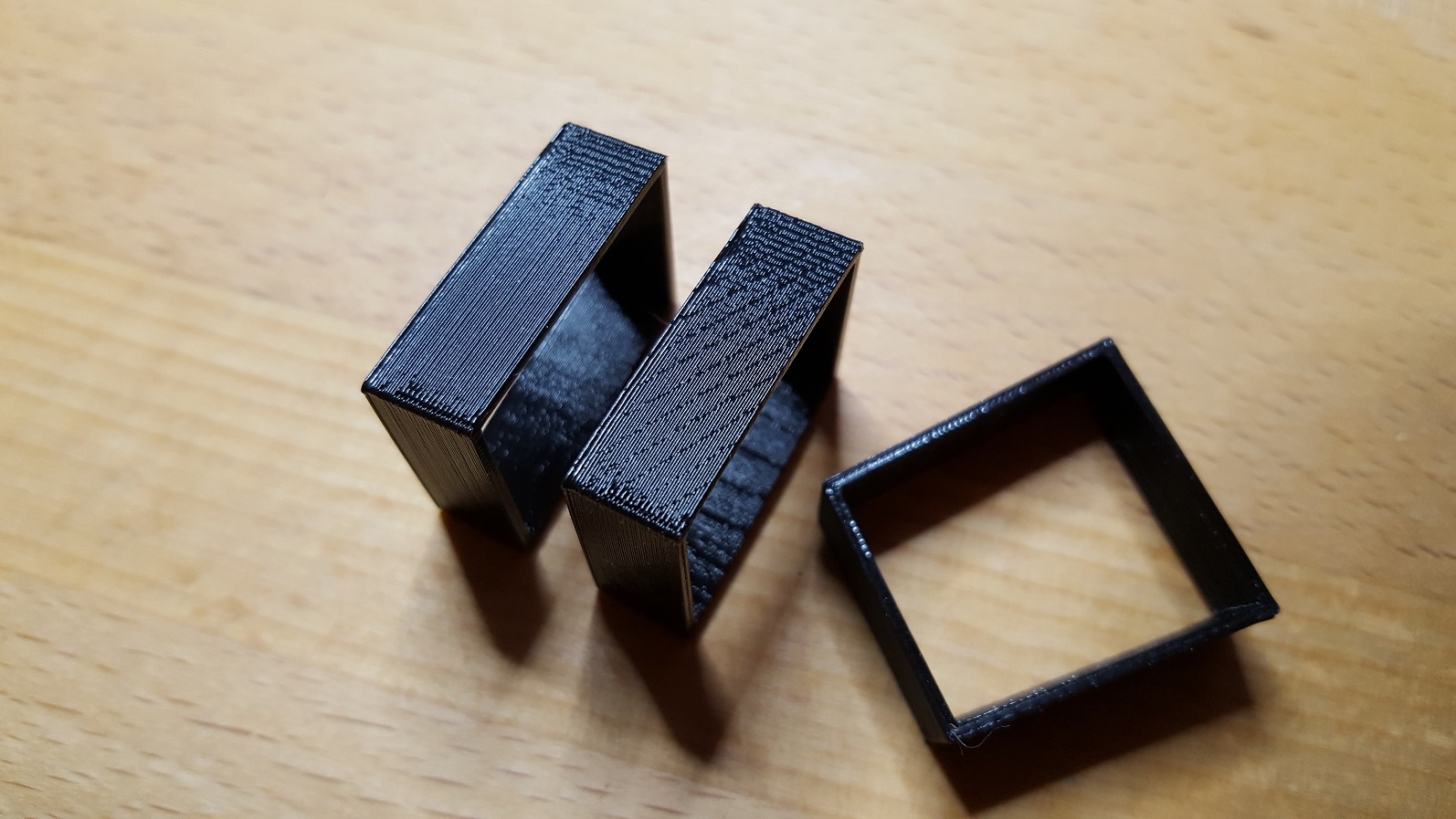
The item in the middle is printed without the diode patch (notice the diagonal bands).
The leftmost item is printed with the diode patch (the diagonal bands are gone)
No apologies necessary, and thank you immensely for this tip!
That is some great print quality you are getting there. That tree frog is excellent. You have done a very nice job calibrating your printer.
As you can see from my picture, I am getting some dripping/oozing that is messing up some of the edges of the print. The motor movements and even the extrusion do seem to be smoother with the diode modification. I’ll know after I run a few more prints.
I was aware of the microstepping issue and the fix by switching to fast decay mode with the possible risk of introducing more noise, but did not yet know about the solution with antiparallel diodes.
So I joined the game with my Vertex K8400, as all Stepper Drivers are DRV8825 there and it also runs on 15V like the K8200 (correct me if I’m wrong here)
Halfway through the soldering I noticed something that might be crucial for the success with this mod: The printer in the original linked blog post runs only on 12V and this might turn out to be a problem (not sure yet). The diodes drop 1.4V, but with a 15V PSU 12% are 1.8V, so it would not be enough to eliminate the problem.
So far I only looked at the voltages on my scope as I’m apparently very good at hiding my shunt resistors, so I had to order new ones today.
This is with the mod. The most visible part is of course the switching between low and fast decay mode, [color=#FFFF00]but I think the actual microstepping problem is in the gaps where the sine wave crosses zero[/color](EDIT: wrong part of the curve), but of course I still have to measure the currents. It could be necessary to put six antiparallel diodes per coil which would be even more space heating (still cheaper than new stepper drivers with their own issues).
To see if it made any difference I connected a 12V brick instead of the normal 15V PSU, but the curve on the scope was the same, so it’s possible that measuring the voltage is just useless in this case.
I think the printer sounds a bit different at low speeds and I can’t see any artifacts in the prints, but I only finished the mod late last night so it might just be sleep deprivation hallucinations
EDIT: If my math is correct then with a 15V PSU, 3.1V nom. 2Ohm motors and 2Amp full scale current of the driver, there are actually 10 microsteps missing in 1/32 mode. The diode mod with 4 antiparallel diodes in series with the motor reduces this to 2 missing steps (maybe 1 if lucky with the diodes)
Well, there’s no way I’m getting any useful current measurements out of this any time soon, because there’s just too much noise for my equipment. And as much as I’d like to have a rilly nice current probe, considering that one of those costs way more than my printers and scope combined … nope.
But I can confirm that choppy movement at slow speeds is completely gone and I’m hearing a lot of (good) frequencies that weren’t there before.
To see whether it made any difference I switched the drivers on my second printer from mixed to fast decay mode:
(drove me almost crazy getting that little wire on there)
Result is that there is absolutely no movement difference between fast decay mode and the diode hack, BUT the noise from fast decay is annoying as f***. You certainly know that frizzy sound when the Z-Axis is held between steps … on fast decay it’s there all. the. f***ing. time!
The only advantage is that it’s basically for free, but really easy to smear solder all over the pins and spend the next 30 minutes trying to clean that mess up (not that it happened to me … cough)
Hi,
could someone make me a shopping list for doing the X and Y axis with drv8825 stepper drivers, and the Z axis i changed to a Pollulu, its making the clack sound ever time it powers up to make a movement up, ive tried to mach the layer height so it would sit on full steps, no succes tho, the noise is reduced, but then gets louder again for 10 layers, then goes softer the following 10 layers etc…
I have a TR8x2 leadscrew on my Z axis and im using the same steps per mm as original, i think the red pollulu chip is half the steps the original was.
I didnt know anything about stepper drivers and G-code or firmware before last week, I just saw the red pollulu chips where 1.5€a piece and read that they can handle some more current, i thought since the pitch of the TR8x2 leadscrew is more the motor could use some more juice.
Ive also installed one of the red chips on to the extruder, the original K8200 one, and running it at 625 steps per mm, its slightly overextruding, but thats on purpose cus the parts I print need to be strong and functional.
Since ive changed the chip of the extruder its never jammed or grinded again, so im very happy i took the chance on that.
The Z-axis clicking sound i have now is however so ducking annoying, PLEAZE help me make a diode board for it !! pretty please…
Afterwards i also orderd 4 DRV8825 chips, but ive learned they are only good for the X and Y axis, so ill be changing those , and keep 2 spare ones.
Im a total noob when it comes to electronics, the scemetaics are like chinese for me. If someone could make some good pictures and give me the specs of the parts i need to buy to make them ill be able to pull it off tho.