eichal
January 16, 2018, 7:20pm
1
Calibration results:
CH1 offset at 2V/div : 179 FAIL
What is causing the failure?
eichal
January 16, 2018, 8:24pm
2
I found that the ic chips were not fully in and here is the results after pushing them in
Calibration results:
CH1 offset at 2V/div : 77 FAIL
eichal
January 16, 2018, 8:26pm
3
Voltages at position
VEL255
January 16, 2018, 9:37pm
4
Please check that there is -5.2V on pin 4 of IC2.
eichal
January 17, 2018, 5:33pm
5
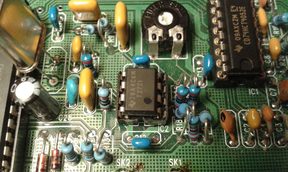
Thank you for the feedback and the photo.
IC2 has correct orientation.
0.709V on PIN 4.
Is there anything else I need to check?
Mean while I will check solder joints and tidy up.
VEL255
January 17, 2018, 6:13pm
6
eichal:
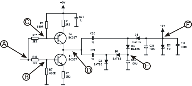
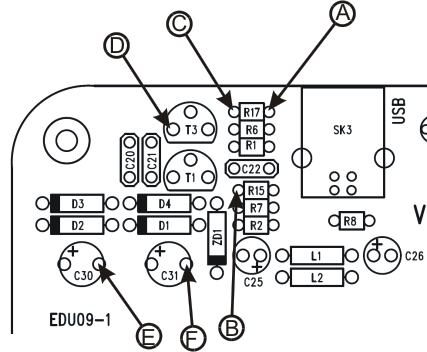
F=-5.2V
This voltage should be found on pin 4 of IC2 too.
eichal
January 17, 2018, 6:21pm
7
point F is now 0.709V, when I measure at point F with ground of multimeter on the negative point where two oscillicope leads are.
eichal
January 17, 2018, 6:26pm
8
5.12V over zener when power is on.
eichal
January 17, 2018, 6:29pm
9
I now have -5.2V at IC2 pin 4. I have not changed anything so confused.
eichal
January 17, 2018, 6:41pm
10
Hi
One other point is that I am using a USB 3 connection.
Does this influence the board?
At present I have all the correct voltages at points A through to F and at IC2 pin 4.
Calibration results:
CH1 offset at 2V/div : 179 FAIL
VEL255
January 17, 2018, 6:50pm
11
The USB cable can be connected to USB 3 socket of the PC without any problem.
eichal
January 17, 2018, 6:52pm
12
Well bad soldering is sure a possibility.-)
VEL255
January 17, 2018, 6:54pm
13
Please check IC1 orientation.
eichal
January 17, 2018, 6:55pm
14
Notch is facing the capacitor bank.
eichal
January 17, 2018, 6:57pm
15
Calibration results:
CH1 offset at 2V/div : 77 FAIL
VEL255
January 17, 2018, 6:59pm
16
This result may indicate that there is no +5V on pin 8 of IC2.
IC1 orientation seems to be OK.
eichal
January 17, 2018, 7:03pm
17
+5.027V is on PIN 8 of IC2
eichal
January 17, 2018, 7:04pm
18
alibration results:
CH1 offset at 2V/div : 77 FAIL
VEL255
January 17, 2018, 7:09pm
19
OK - Please check the voltage on pin 1 of IC2.
VEL255
January 17, 2018, 7:13pm
20
Here are the voltages measured on all IC2 pins:not running.
On IC1 pins the voltages should be:
These voltages are measured when the PC software EDU09 is running.
On IC1 pins the voltages should be:


