There can be several issues causing horizontal banding. If it’s going all around the part - i.e. a whole thinner layer, often followed by a thicker layer - then it’s probably Z-axis related. If it’s starting mid-layer and especially always on the same side of the part, then X/Y-axis.
There are several things than can cause Z-axis related problems: The threaded rod, the vertical linear bearings and software settings. And some things may look like z-axis related problems. Like a partially clogged nozzle or a feeder problem, either by filament stuck on the spool or contaminated pulley.
I did several tests the last two days to fix this problem. This was after I cleaned the nozzle (it was worse before):
-
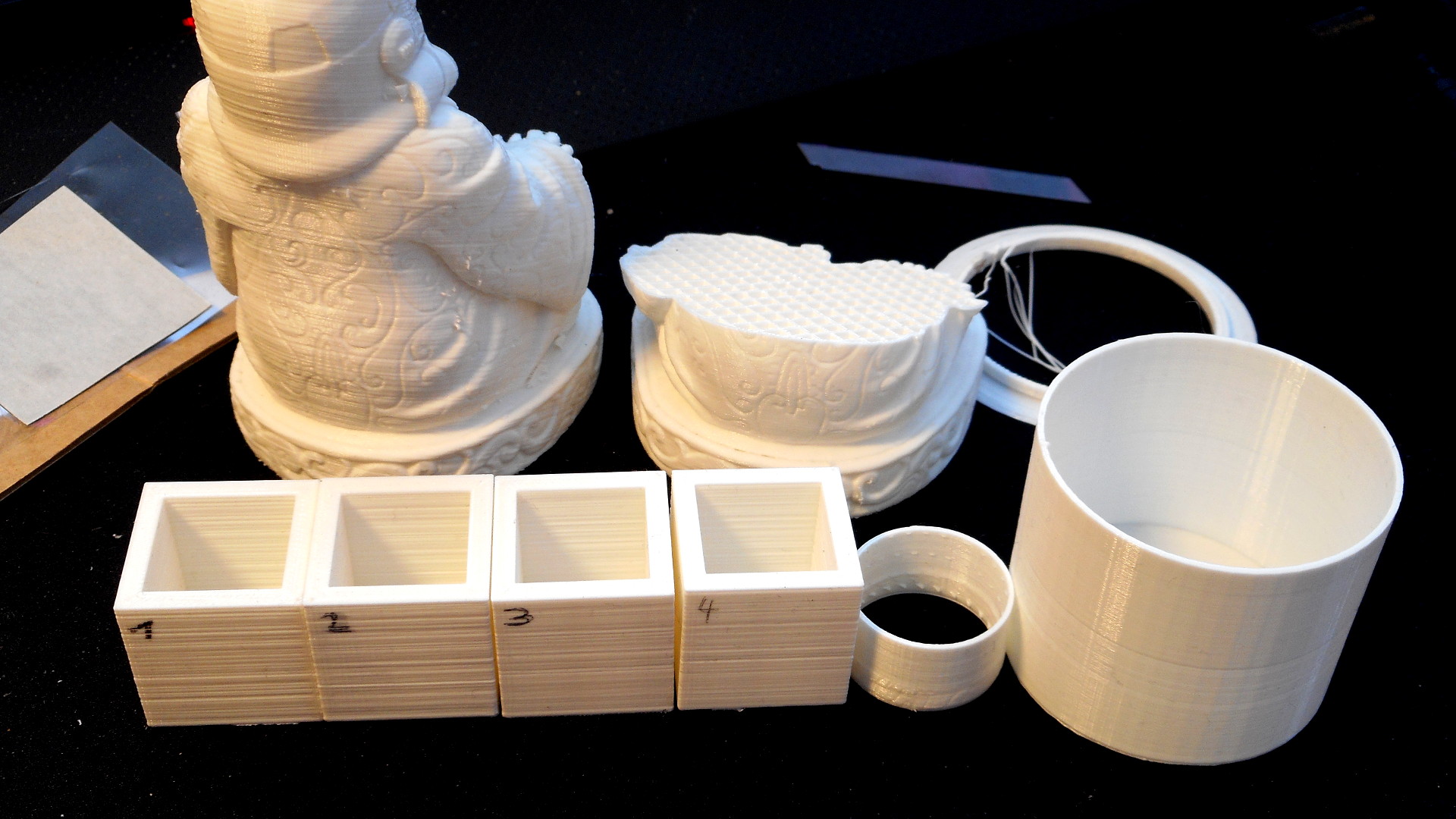
The starting point after cold pulling ashes caused by the 210°C out of the nozzle. (The cubes are 25mm by the way)
-
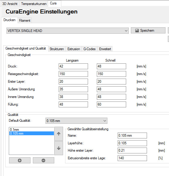
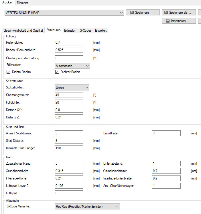
After changing all settings related to the z-axis in Cura to be multiples of 0.0075mm. The reason is that one step of the z-axis is 0.0075mm (200 steps, 1.5mm per revolution). Cura doesn’t actually know that. Having a value that can not be divided by 0.0075 results in one step more or one step less, i.e. one layer slightly over-extruded and one layer slightly under-extruded. It’s not so extreme, if a sligtly over-extruded layer is followed by a normal one, but still noticable.
Part No.2 doesn’t look actually better, but on the corner there was now a regular pattern, exactly every 1.5mm (one revolution of the z-axis threaded rod)
-
After aligning the stepper motor to be in line with the nut in the carriage. I did this by adding a z-axis stabilizer on top without the bearing and measure, how the rod moved when going up and down. I needed a spacer of 0.6mm between case and motor mount to eliminate any movement of the rod in the y-direction
-
After adding a z-stabilizer on top … didn’t do anything really.
-
(not shown - don’t know where it went): The threaded rod also moved slightly left and right. The reason was that the mounts on the case were not parallel and slightly too close to each other. On the carriage the rod-distance was 111.65mm, top and bottom around 111.3
I also noticed with the threaded rod removed that the linear bearings had a really harsh movement and were binding so much, that at some positions I didn’t even have to hold the build-plattform. It was stuck and I had to actually add a little pressure to make it move down.
So I sat down and took the whole z-axis apart. The main problem now was, that the bearings on each side were not perfectly aligned, which is no wonder, because it’s almost impossible if done the way, the manual suggests. This would not even matter, if the bearings were good. The ones in the set are mediocre at best. I have one good one, two “kinda okay” ones and the last one is really bad, but I noticed that it’s almost okay in one direction, but binds a lot in the other, so now it binds on going up - which I don’t really care about.
Took me about an hour to align everything and another 30 minutes to get it back into the case. The way I did it, was to leave the bearing mounted to the carrier (the metal part, not the plastic with the nut for the threaded rod) of the build platform with the screws tightened as hard as possible with the plastic clamps.
Took quite some time and cursing, but was well worth it. (Still ordered better bearings, in case the problem reappears)
The two round ones are after that procedure. The banding is caused by manually changing the extrusion-rate, to find the sweet spot. That’s because I noticed that the white PLA needs actually more extrusion than the black one I used before. This caused an amplification of the z-axis problems.
The top 20 mm of the bigger cylinder are the settings I’m using now.
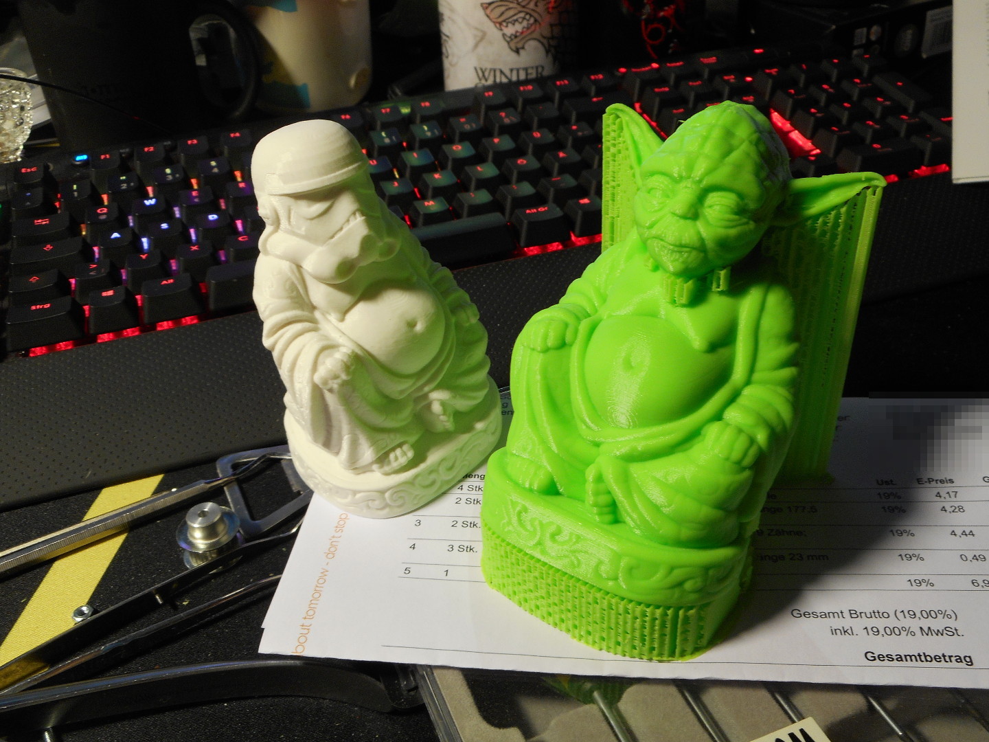
The lefte Trooper-Buddha in the background was after the test-cubes, the right one after the cylinders. (My computer decided to restart, while I was printing via USB - very nice, thank you Windows Update).


 I am also removing the aluminum plate and replace it with the custom heated bed from Marlak which also reduce the weight


 They are great! I will never use again those LMxxUU bearings!