X Command Waiting

On mine I got lucky and was able to solder it back on.
Like I said I did not do this but thought I would have to.
I saved the pictures in case I made another bone head move.
LOL.
I hope this helps you.

yes, thank this is helpful. May I ask how you soldered it back? put the thingy on top of it and pressed with a soldering iron on top of it? (I am trying to do this procedure right now)

First I tinned the pads then I aligned the tabs and super glued them making sure the pins were straight.
Then soldered the pins It was kind of hard since I kept getting shorts.
It took awhile but finely got it done.
I kept metering it in every way possible to make sure there were no shorts.
Since then I mounted a Raspberry pi on it with Octoprint and cable tied the cable to the frame so nothing would snag on it and pull the cable. It’s kind of nice the printer has Wifi I also mounted a web cam on it so I can watch and control it from my phone tablet of computer. Octoprint does have Cura so you can send the STL out to it but I like to slice it on my conputer. The Interface is web based very ease to use

so you superglued it… I though of super-gluing it myself. Then I though, I’d just heat it from above… but I do not think it was as successful as I though. I think I’ll just try to get those cables the way you have in your picture. If that does not work, I’ll just take them out… I thought it would be just enough to touch the points (without soldering). I placed the thingy, and checking with the multimeter, whether there’s a connection between the connection points in the picture and the cable.

Your advice is very helpful. Having this done is getting my top priority. Also doing octoprint and cura would be really nice.

Would you interested in continuing it over the chat? I am available over skype:

https://join.skype.com/guHU9UJ3t7YY

I hope this is not too much to ask…

Hi @Wrong_Way,

That photo of yours was helpful. I soldered it they way you showed to me and was able to connect to the board from windows. This solved the broken usb thingy. Unfortunately, this brought me to the ground zero: I can connect to the board, but the repetier says : X commands waiting.

I have uploaded the video what the board shows when I connect power supply and usb to youtube:

https://www.youtube.com/watch?v=h-xOn4KPudk

Is there anything else I can try out?

Cheers,
Arturas

Additional infos how I get from this “Waiting for Command X” unfortunate state every now and then: (1) I connect the 3d Printer to windows through usb, (2) I connect the 15V power supply, repetier gets into “6 commands waiting” state. (3) I unplug the power and plug the power (leave the usb connected). the thing continues to be responsive for a while. Comments?

The video:

https://www.youtube.com/watch?v=5Kpcc6xoYgI

Cheers,
Arturas

Arturas
Go into the printer settings with the exception of the com port ever this should match this picture. I am thinking “Reset on Connect” is not set to disabled

Hi @Wrong_Way,

thanks for coming back. Here’s the window:

You cannot imagine how many times I checked that bloody window! :slight_smile: The manual says the “receive cache” needs to be a smaller value (I believe 63), but you pointed out in a previous post that I need to set it to 127. So I did.

Wait. In my window it says “disable and reconnect”. In yours only “disable”. Let me check the laptop I am printing from. I’ll repost the screenshot once the printing is done (I am printing the v5-14clip.stl, a part for the fan part). In this post:
Untitled

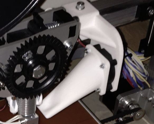
the fan parts look fancier. You’ve got the code maybe?

Cheers,
Arturas

I noticed in your video that you connected the software then disconnected the power then reconnected it that might be a problem.
Also do not try to print the way you have the power connected. That jack can not handle the current draw and will melt.
If you have printed like that the jack maybe one of the problems.

So that jack might not handle the current draw, huh? This does not sound good. Because I also wanted to test the abs printing, and that would draw even more current (the bed needs to be heated to over 100 degrees C).

I started using the jacket, because it is bloody hard to unscrew those tiny screws and screw them up again, every time I get that bloody “wait for command X” problem. But once you mentioned, I could have plugged and unplug the power supply from my 220V net. I understand that this is not the same as re-plugging the thing on the 12V side (compared to 220V side), as there huge initial oscillations to at the time the power supply gets its initial voltage/current. But it is worth trying. I’ll try this as soon as the print finishes (another 40min to go).

Cheers,
Arturas

There is a black reset button at the top of the board as well.

Hi @Wrong_Way,

it is extremely embarrassing, but I must say that the printer settings on my laptop (on which I am printing the print outs) had the wrong settings. Once I put into the correct ones, I am not able to reproduce that “waiting command X” error anymore (which is good news).

To my defense I must say that the options were correct on my desktop machine. In this case the usb connection problems (too long cable, motherboard, anything) could have resulted into the problem.

Bloody hell. I suppose this thread could be put aside for a while. Let me start a couple of other ones, especially, on the cuda part :slight_smile:

Cheers
arturas

The cable length can be an issue.
It sounds as if things are moving forward.

I am in emotional roller-coaster right now. I have a feeling that the board is dead or about to die.

Just finished printing the parts for the fan. the part surrounding the extruder went smoothly. The part that attaches to the frame was harder. It kept destroyting the first three layers, so I decided to print those extra slow (50% of the initial speed). After the three layers, I gave 100% speed. The board’s temperature was going from 45C to 55C. That was different to the previous print outs. Why would it not stay at 50C?

Afterwards I started extensive testing with the printer settings and whether I need to replug the 15V power supply. Quite a few times it went with flying colors and then the error reappeared. I noticed that the LEDs were not as light as before (well, they got always dimmer as I plugged the 15V power, but this time a lot dimmer). So I took all the connections out and reattached only usb and power supply. Then I noticed that the part labeled 7805abd21rdnf40g (right to the 15V power supply) was getting rather hot (over 40-50C). If that chip is responsible for stabilizing voltage/current, I can imagine under what kind of load the poor guy had to operate. Cause the power supply is oscillating between 13 and 15.5 like crazy.

hot33
@Wrong_Way, do you think, you could measure the open circuit voltage of your power supply? Cause if I connect it to the machine, it is pretty stable, if I disconnect it, it starts fluctuating wildly :frowning:

I’ve tested the current flow. Without any load it takes between 0.5A to 1.0A. This is 15W. Uploaded the video:

Yes, it is the voltage regulator. I suppose it produces 5V (among other things):

http://radiocom.dn.ua/image/data/pdf/L78xx_STM.pdf

I’ve measured the OCV on the ouput pin. It is 5V… then it drops to 4.2V. Then it drops to 0V. And then it repeats itself. The thermal protection must be kicking in. I am depressed beyond imagination.

I just checked mine.
It’s solid 15Vdc plugged or unplugged

Thanks, mate. This must be the cause. I need to contact velleman, I suppose. You know any good email address for that?

Cheers,
Arturas

Hi!

for support or repair please issue a ticket at http://support.velleman.eu

Best Regards,
VEL337

I opened a ticket. And got the response:

Please return the product for inspection/repair/exchange to your Velleman distributor or directly to the Velleman Repair Department

Legen Heirweg 33
9890 Gavere
Belgium

Make sure to include a detailed fault description, remove all add-ons and include proof of purchase if you want the item to qualify for treatment under warranty conditions.

US residents, please call (817) 284 77 85 to obtain an RMA#

so it seems that for velleman the ticket is closed. Who will take care of the shipment costs? Do I have any questions? Does not seem that velleman is interested in that. They just closed the ticket. Most probably it took like 5 minutes to read it and here we go. Issue resolved. What should I do in case I want to continue they say? Included problem description on detail level in later communications. Because the ticket is closed already.

Let’s give the benefit of the doubt for the Belgians:

https://www.thelocal.fr/20180124/decoding-the-french-are-they-really-rude

I think the cause will be one of the controllers of the drives. I’ve rechecked all four of them one by one:

and tried to (recalibrate/)set the 0.55V for all of them (it is pretty hard to do so as turning just a slightly bit increases the voltage from 0.54 to 0.55 or from 0.55 to 0.56V. The current settings for three of the controllers is 0.55-0.56V except one of them, which is 0.53V. Turning the adjustable resistant (increasing the voltage) for that one over 0.53V shuts downs the circuit. I’ve been adjusting the resistors with all of the controllers in (compared adjustments, where only one is in, as the voltages drop quite a bit with all four in)

Interestingly enough, if I adjust them with only one in, the current that is pulled varies individually from one controller to the other. Two of the controllers pull 0.24A, one pulls 0.18 and the one that messes up the whole thing with voltages over 0.53V pulls 0.5A. If I put all of them in and with 3 of them at 0.55V and one of them at 0.53, the overall consumption is 0.9-0.7A at the beginning but slows slows down to 0.4-0.3A in a minute or two.

What does the voltage mean? Can it vary from one to the other (0.55-0.53)? Should all have the same (all have 5.0V or 5.1V, etc.)?

Additional comment on the smell. Does it smell a bit if you print? Cause in my case it does slightly. I always connected this to the cooking PLA, but the smell also appears even if I don’t attach anything to the CPU board. Anyone having similar experience? This must be the voltage regulator L78xx heating, right the chip? (L78XX is over 120C in my case.)

In those tests I have used an external adjustable power supply set at 15V