When i make a bode plot of an amplifier, there is always an increment of
gain above 1 kHz. mostly about 1 to 3 dB.
When i put the generator direct on the scope there is also a
wrong plot with increased gain above 1 kHz.
I have calibrated the scope first of course.
What happens? i have tested with several leads and probes, but no
difference. Is this a calibration isue? defective? dead component?
How to solve this?
Thanks in advance.
Arie
Could you please post some output data. - In the File menu of the Bode Plotter select Save Data.
Connect the generator output directly to the input of the PCS100.
Is the increment of the amplitude exactly at 1 kHz or is the increment slowly increasing above 1 kHz? On what frequency range this increment appears?
Hi,
I send you some data and a screenshot picture.
Yes, the output of the generator was directly attached to the input
of the scope.
It is slowly increasing above 1 kHz.
It appears in the mode 10Hz…100kHz.
This is the result of a new bodeplot.
I seems that the outputlevel of the generator changes.
As i look at the scope window during testmode, the amplitude increases too.
How can i send you the picture?
And of course…
Hz Vrms dBV
10.0 1.738 4.801
20.0 1.736 4.790
30.0 1.733 4.777
40.0 1.732 4.769
50.0 1.729 4.757
60.0 1.730 4.758
70.0 1.729 4.755
80.0 1.728 4.753
90.0 1.727 4.748
100 1.726 4.742
200 1.732 4.768
300 1.730 4.759
400 1.733 4.776
500 1.733 4.776
600 1.735 4.784
700 1.736 4.793
800 1.737 4.796
900 1.740 4.810
1000 1.744 4.828
2000 1.769 4.954
3000 1.802 5.113
4000 1.834 5.268
5000 1.865 5.415
6000 1.891 5.534
7000 1.912 5.629
8000 1.929 5.705
9000 1.942 5.765
10000 1.953 5.811
20000 2.000 6.018
30000 2.011 6.066
40000 2.017 6.093
50000 2.018 6.097
60000 2.017 6.095
70000 2.018 6.098
80000 2.015 6.085
90000 2.015 6.085
100000 2.030 6.148
It seems that the results you got are not typical.
In this image there is the blue trace showing the results I got with PCG10 and PCS100.
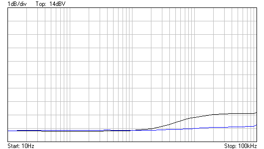
The black trace shows your results.
I do not know the reason to this.
Could you please make another test run up to 1MHz.
You can send the data as you had done (using copy and paste).
Select the pasted text and click the “Code” button to keep the formatting.
If you like to send images you have to upload it to some free image hosting service e.g. servimg.com/.
You’ll get a link to the image.
Copy and paste the link. Select it and click “Img” button.
I made the test to 1MHz
This is the result:
Hz Vrms dBV
100 1.757 4.893
200 1.755 4.884
300 1.755 4.885
400 1.756 4.890
500 1.760 4.913
600 1.761 4.914
700 1.763 4.924
800 1.765 4.935
900 1.767 4.946
1000 1.772 4.969
2000 1.809 5.147
3000 1.851 5.350
4000 1.898 5.565
5000 1.960 5.845
6000 2.004 6.036
7000 2.040 6.191
8000 2.075 6.342
9000 2.098 6.438
10000 2.118 6.516
20000 2.216 6.913
30000 2.239 6.999
40000 2.249 7.040
50000 2.249 7.039
60000 2.254 7.059
70000 2.255 7.063
80000 2.249 7.041
90000 2.252 7.051
100000 2.271 7.124
200000 2.281 7.162
300000 2.286 7.180
400000 2.289 7.192
500000 2.289 7.194
600000 2.286 7.182
700000 2.288 7.188
800000 2.288 7.191
900000 2.286 7.182
1000000 2.294 7.213
I think, that the generator is increasing the amplitude
can this be solved with calibration?
I think the problem is in the PCS100.
It seems that the displayed amplitude of the PCS100 is slightly increasing at the range 1kHz to 1MHz.
In your case the amplitude changes quite a lot.
Here my results: the blue trace. Your result is the black one.
Do you have any possibility to measure the PCG10 output amplitude (other than the PCS100) ?

Hi,
Yes, i have:
Fluke TRMS 87 meter
Analog oscilloscoop 20 MHzx2
Philips PM2454 AC millivoltmeter 2 Hz…2MHz.
What do you sugest?
You may use the Fluke 87 up to 200kHz.
You can also check the amplitude stability with the Philips PM2454 up to 1MHz.
Just manually step through the frequency ranges of the PCG10 and check if there is any change of the amplitude.
Then connect the signal also to the PCS100.
In View menu select “RMS Value” to be displayed.
Compare the readings from Fluke 87 and Philips PM2454 to the RMS reading on the PCS100 screen.
If Fluke and Philips display stable reading and if the reading on the PCS100 screen changes then the PCS100 needs possible re-adjustment.
Hi,
You are right.
The PCS100/K8031 is not working properly.
Both the Fluke and the Philips show the same value.
At 10kHz the fault is +0,58 VRMS !! With 3,003VRMS input.
How to handle to solve this bad behavior?
Can i readjust it myself?
Do you have a serviceguide?
On the CD (Velsoft 2) there is a calibration software and instructions in the folder: D:\Product Manuals and info\Velleman Instruments\PCS100 1ch PC scope\Test soft Pcs100
On Velsoft 3.0 CD: D:\Technical info\PCS100_K8031 1ch PC scope\Test soft Pcs100
- Install the software.
- Connect the PCG10 to PCS100.
- Run the calibration software.
- Follow (carefully) the instructions to adjust the trimmers.
Oke, thanks for advice but
How to obtain the VELSOFT 3.0 cd ?
Can i download it?
THanks !
Arie
You may locate the test and calibrate software on the CD you got with the PCS100.
On the Velleman Software disk:
D:\Velleman Instruments\Technical reference\PCS100\Test soft Pcs100
On the Pc-Lab 2000 disk:
D:\Technical and Info\Pcs100\Test soft Pcs100
BAD luck.
I found the software on the cd that was delivered with the set.
Calibrating the PCG went fine.
The next steps for the PCG100 are difficult
Step 1 no problem
Step 2 no problem, i was able to set RV1 at the right setting
Step 3 Problem
“Floating point overflow” pc error
and calibrate status screen says:
Calibration results:
Offset at 3V/div 93-163 : 280 FAIL
Correction at 1V/div <30 : 51 FAIL
Trace position high 160-200 : 255 FAIL
Trace position middle 108-148 : 255 FAIL
Trace position low 55-95 : 255 FAIL
Correction at 20us/div <30 : 101 FAIL
Correction at 10us/div <30 : 101 FAIL
Correction at 4us/div <30 : 101 FAIL
At this point further calibration steps are not wise to proces says the manual
Strange problem.
The frequency response problem may be solved by the adjustment of CV1 and CV2. Those are done in the steps 4 and 5 of the test program. You didn’t reach those adjustments due to the calibration problem in test number 3.
You may try following:
Run the test software.
Double click the text “Reset default settings”
Then go to test number 4 by double clicking the text “Adjust CV1 until the wave top is straight line”.
Do the CV1 adjustment if needed.
Then go to test number 5 by double clicking the text “Adjust CV2 until the wave top is straight line”.
Do the CV2 adjustment if needed.
Close the test program.
No good feeling…
Steps 4and 5 give not a complete sharp edge after adjusting.
The top of the signal was out of range, with offset -5v
i was able to check de top of the waveform.
Step 6 is a problem, i can’t set to 1,00VRMS in 1V/div there is
about 2,604 VRMS. in3V/div there is about 10,778VRMS.
After all adjustments there was still a bad response in bode plot
Hz Vrms dBV
100 1.298 2.267
200 1.302 2.290
300 1.302 2.290
400 1.303 2.300
500 1.304 2.308
600 1.306 2.320
700 1.308 2.333
800 1.310 2.342
900 1.313 2.362
1000 1.317 2.388
2000 1.349 2.600
3000 1.390 2.860
4000 1.432 3.116
5000 1.473 3.364
6000 1.508 3.569
7000 1.538 3.739
8000 1.562 3.874
9000 1.582 3.985
10000 1.599 4.076
20000 1.670 4.455
30000 1.691 4.563
40000 1.699 4.603
50000 1.701 4.616
60000 1.704 4.627
70000 1.704 4.629
80000 1.704 4.631
90000 1.702 4.620
100000 1.715 4.685
200000 1.722 4.720
300000 1.725 4.737
400000 1.731 4.767
500000 1.729 4.754
600000 1.733 4.773
700000 1.733 4.773
800000 1.735 4.785
900000 1.733 4.776
1000000 1.733 4.778
I saw also a offset with AC/DC/GND switch in GND setting.
Please delete the WinDso.ini file from the PC-Lab2000 program folder.
Then start the PCS100 normally. The self calibration occurs.
This self calibration is important to do after the adjustments you made.
After the self calibration, to check that everything is OK, please do the following tests:
-
Connect the PCG10 with a direct cable to the scope input.
-
Set square wave of 2kHz, 10.0Vpp to the PCG10
-
Set the scope to 3V/div, 0.1ms/div, DC coupling
-
Check that the wave top and bottom are straight lines on the screen.
-
Set square wave of 2kHz, 1.00Vpp to the PCG10
-
Set the scope to 0.3V/div, 0.1ms/div, DC coupling
-
Check that the wave top and bottom are straight lines on the screen.
-
In the View menu of the scope check the “RMS Value”.
-
Set Sine wave of 2kHz, 1.00Vrms to PCG10 (Type 1.00 to the Vrms value display box and press Enter button.)
-
Set the scope to 1V/div, 1ms/div, DC coupling
-
Check that the RMS value displayed on the scope screen is 1.00V (+/- 0.05).
YES this works!
I have adjusted CV1 first and second CV2
Last RV2 for 1,00VRMS
Now the line is straight between 0,2 or 0,3dB
Thanks for your help!
Some new data
Hz Vrms dBV
10.0 1.758 4.902
20.0 1.755 4.887
30.0 1.756 4.888
40.0 1.751 4.868
50.0 1.754 4.879
60.0 1.751 4.866
70.0 1.750 4.862
80.0 1.752 4.869
90.0 1.751 4.864
100 1.753 4.875
200 1.751 4.868
300 1.751 4.867
400 1.748 4.853
500 1.753 4.874
600 1.754 4.881
700 1.755 4.885
800 1.757 4.897
900 1.756 4.891
1000 1.758 4.900
2000 1.763 4.926
3000 1.774 4.977
4000 1.783 5.023
5000 1.791 5.062
6000 1.796 5.084
7000 1.799 5.099
8000 1.801 5.109
9000 1.798 5.093
10000 1.804 5.124
20000 1.785 5.033
30000 1.779 5.005
40000 1.780 5.008
50000 1.771 4.966
60000 1.771 4.964
70000 1.769 4.955
80000 1.766 4.939
90000 1.766 4.938
100000 1.777 4.994