Why isn't the digital output voltage of k8055 = 5V?

Good day everyone. I’m new here, i am doing a project. My project is about building a robot that can move around (front and back using a DC motor). The unusual part of my project is that it uses a computer motherboard as the main processing unit instead of PIC. Here’s a list of what i’ve done.

~Got a mini ITX form factor motherboard ( very small computer motherboard, uses window XP, running fine)
~12V battery and DC to DC converter (portable power supply that really works)
~Relay circuit and 6V DC motor (motor driver using L298, tested and it works)
~k8055 (to send output to control the motor through the relay)
~A chassis that holds all the above together.

Once the power button is pressed, the computer is suppose to boot the OS and autorun a program (which i need to write later) that will activate the motor. The objective is to allow the robot to move forward and backward for a certain amount of time that the user desire.

My main problem is the K8055. while testing it using the GUI program in the CD provided, i notice the output voltage of all 8 digital outputs are 0.6V for logic “1” and ground, 0V for logic “0”
Shouldn’t logic 1 be 5V?

0.6V is too low and it can’t start the motor. The L298 motor driver require 5V for logic ‘1’ to turn on the motor.
I’ve tested using the analog output of k8055, the maximum output is 4.5V, and it is enough to turn on the motor.

using Digital multimeter, the voltage at the digital output right before the resistors are 4.5V, after the resistor, the voltage drops to 2.0V, and once passed the LED, the voltage becomes 0.6V. (all voltage shown are with reference to ground of the k8055)

I’ve checked the soldering and the components used, it seems to be ok (the soldering was done by a skillful electronic shop, i doubt they will make any mistake)

is there an option to change the output voltage through software? or my k8055 is defected?

Please help…i’m really close to completing the project, i just need the digital outputs to work.
You have very interesting project!

It seems your K8055 card is OK.
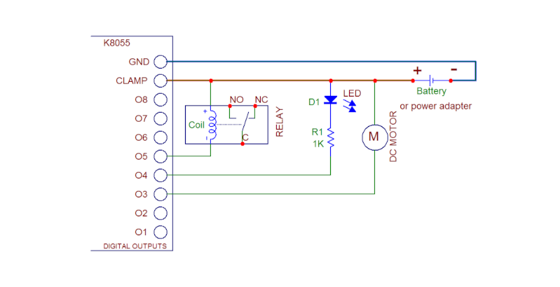
There is no voltage output from the K8055 digital and PWM outputs. These outputs are open collector NPN transistors. You have to use external voltage and add pull up resistors from the digital outputs to the external voltage.

Here are some other examples of connection:

You might want to [color=#0000BF]look at this thread[/color], describing a method to use the 8055’s PWM output, and one digital output, to provide a variable speed and reversible drive to a DC motor…

Thanks for the reply.

VEL255, i never knew the k8055 can control a motor directly.
this means my relay circuit is useless.

So according to the picture you show me, i just need to connect the battery(-ve to ground, +ve to clamp), and the motor (one terminal to battery, and the other to any one of the digital output, example output 1.)

So when i turn on digital output 1, the motor will spin? is it that simple?
Can i ignore the relay, diode, and the resistor in the pic?

[quote]So according to the picture you show me, i just need to connect the battery(-ve to ground, +ve to clamp), and the motor (one terminal to battery, and the other to any one of the digital output, example output 1.)

So when i turn on digital output 1, the motor will spin? is it that simple?[/quote]You are absolutely right. The only limit is the motor current. Should be <100mA according to the K8055 specs.
There is a transistor array ULN2803 at the digital output. You may check its specs here: datasheetcatalog.org/datashe … 828_DS.pdf
If you look the datasheet of the ULN2803 you’ll see: Collector Current – Continuous IC 500 mA.
The specified 100 mA current/channel is very well in the safe area.

[quote]Can i ignore the relay, diode, and the resistor in the pic?[/quote]Yes, you can. They are just as examples of different connection possibilities.

thanks VEL255,

your explaination is very clear.

I’m almost done with my project. Previously, I was struggling with the programming part.

I’ve found several demo program (.exe) from the web, but their pretty much useless for me
since they are just a GUI to control the k8055 output. Everything has to be done manually.
My robot needs to be automated. (able to move on its own once it’s turned on)

I’ve tried programs written in C#, C++, lab view, VB but they’re all the same, just different GUI.

The best one i’ve found is by using a program called EventGhost.
With the k8055 plugin, the user can easily program the k8055.
Example, if input 1 = high, then do ouput 1 = high. Insert delay, repeat, loop, etc etc.
Just by using mouse clicks, no typing needed.

Its really simple and powerful. Just want to recommend people who are doing project similar to mine.

eventghost.org/

[quote=“VEL255”]You have very interesting project!

It seems your K8055 card is OK.
There is no voltage output from the K8055 digital and PWM outputs. These outputs are open collector NPN transistors. You have to use external voltage and add pull up resistors from the digital outputs to the external voltage.

Here are some other examples of connection:

[/quote]
Hi,

I got my K8055 board yesterday and have started playing with it and have a similar problem which I don’t know how to solve.

I have a robot arm from the '80s which was a pretty ‘dumb’ control board designed to take an 8-bit input from a PC (typically the parallel port). As the K8055has 8 digital outputs I figured this would be perfect, but can’t get it working at this stage.

I suspect this is due to the voltage issue.

The robot elctronics has a 10 line input, designated as Ground, +5V and 8 binary inputs.

I have wired the controller with the ground to digital GND, +5ve (with external 5ve source) to Clamp, and the 8 binary lines to the 8 digital outputs.

Based on your comments above, I suspect I need ‘pullup’ resistors, but don’t really know and don’t want to break things by experimenting. Can you suggest what I might need. If you need further details (e.g. the robot circuit diagram, etc I can point them out on the net).

Thanks,
Craig

The pull-up resistors will be connected between the digital outputs and the positive pole of the external power supply.

Hi Vel255,

Thanks for the rapid response. SO I assume they can be 1k resistors as per the circuit diagram quoted. (I’ll go buy some at lunch time).

Cheers,
Craig

If 1k used and the external voltage is 12V then there will go 12mA current. This is very well within the specs of the K8055. - The maximum specified current to each digital output is 100mA.

Hey there,
Sorry to reply to an old post, however I was wondering the same thing and stumbled across this post. A question in addition to the above… as I need 5V on the digital outputs, which coincidentally is roughly what the USB port is providing to the K8055 internally, would that mean its safe enough to feed the 5V’s coming out the analog port DAC1 direct to the CLAMP and analog GND direct to digital GND? In other words, effectively using the 5V feed from the analog output as the battery feed to the the digital clamp? (that would also mean I can adjust the digital output voltage by controlling the analog outs via software too if needed)
Cheers

[quote]would that mean its safe enough to feed the 5V’s coming out the analog port DAC1 direct to the CLAMP and analog GND direct to digital GND?[/quote]Yes, this is OK.
If you connect the DAC1 to the CLAMP you have also to add a pull-up resistor between the CLAMP and the digital output terminal.
The digital outputs are open collector.

All the GND terminals of the K8055 board are internally connected together.

thanks for the quick feedback!

To clarify (as im a electronics newbie!) if I were using say digital output 1 to run an external solid-state relay and switch 240V AC using the 5VDC, then the pullup resistor sits between the digital output and the relay? or between the clamp and the relay? I assume there should be a pullup resistor on each thing we’re controlling, so should be the digital output correct? Additionally, to help me understand WHY a pullup resistor is needed, my understanding is that the basic functionality of pullup resistor is to ensure that (given no other input) a circuit assumes a default value. Currently when I place a multimeter on one of the digital outputs I still get a reading of 0.2V’s (even though that particular digital output is off) so a pullup resistor ensures that the value is set to 0V or 5V (or thereabouts) and nothing in between, by limiting the current - is this correct???

[quote]so a pullup resistor ensures that the value is set to 0V or 5V (or thereabouts) and nothing in between, by limiting the current - is this correct???[/quote]Yes, this is correct. Just connect a pull-up resistor between the digital output and the external supply plus pole.
If you have only a logic circuit connected to the digital output you can use the DAC1 or DAC2 as the power supply.

The maximum current from DAC1 and DAC2 is limited to 3mA by the series resistors of 1k5 on the DAC outputs.

If the solid state relay works with 3mA you can connect it between the DAC output and digital output.

Hellow,

For this kind of application, i’m watching almost everyday the status of the Raspberry Pi project. Even better than a mini ITX motherboard ! But you will have to learn to use a real operating system (troll :smiley: ).

raspberrypi.org

Well I’m editing this one, as I didn’t understand a pullup resistor - found a site that explained it really well so get it now… :laughing:

Also, this doesn’t make sense? According to your diagram with the relay, the digital output plugs into the relays negative pole?

What I’ve got is a 9V battery (as a test for now) + connected to CLAMP, - connected to GND. I’ve then got CLAMP connected to a 1k resistor then to the + on the SSR. Then I have - on the SSR connected to Digital output 1. Is this correct? It does actually work, just want to make sure its correct.

Unsure on its rating, but it doesn’t work if providing the the internal 5V’s. Multimeter measures only around 2.4V’s (need 3V at SSR) so won’t switch the relay output on (whereas the 9V external battery does) so I assume its just not providing enough current. Looks like I’ll have to use an external power supply for this.

To also clarify - as this had me utterly confused at first, according to the site I read “pull-up” or “pull-down” are just normal resistors - but simply denoted as “pull-up” or “pull-down” depending on where they reside in the circuit - correct?

[quote]What I’ve got is a 9V battery (as a test for now) + connected to CLAMP, - connected to GND. I’ve then got CLAMP connected to a 1k resistor then to the + on the SSR. Then I have - on the SSR connected to Digital output 1. Is this correct?[/quote]This is correct.

[quote]To also clarify - as this had me utterly confused at first, according to the site I read “pull-up” or “pull-down” are just normal resistors - but simply denoted as “pull-up” or “pull-down” depending on where they reside in the circuit - correct?[/quote]This is correct too.