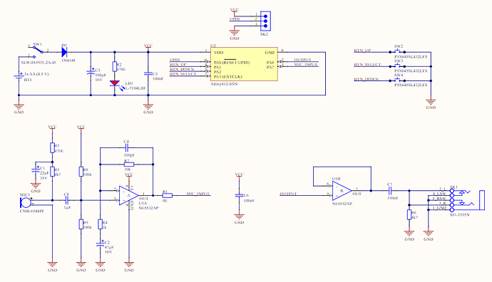
Hi,
I’ve just bought from a local dealer the voice changer kit and I was assembling it with my 7 years old child making him cut the components “legs” after soldering.
Unfortunatelly he pull to cut the C1 and he detached the contacts from the board.
Is there somewhere the electric scheme to know where the C1 terminals are connected so we can finisch and test the kit? ![]()
thank you so much.
So, applied to the board, the + pin of the capacitor to the nearest pin of R3 and the - pin to the negative of power supply?
Or I can connect to the GND of the Mic? I can’t remember which is the - pin of the Mic ![]()
WHat do you suggest? do you have the design of the board?
the - pole of the mic is also the chassis (housing) of the mic.
Best regards,
Velleman Support
Were you able to get this kit working? I built one without issue but the output is absolutely terrible. It is unintelligible and distorted beyond recognition. I am curious if you had the same results?
Yes, got it!
The output is not clear as I expected but It works.
I don’t know if it is a microphone problem or is about amplifier, I had to buy a small speaker with battery to keep it portable.
It takes me a while even to understand the behaviour of buttons. There was no manual abou it.
So central button is to activate/deactivate sawtooth wave or something similar. Then right and left button are to increase/decrease the tone.
