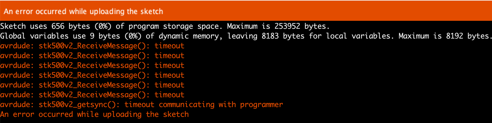
Second part of the story is about; How did the initial flashing of the VMA205 resolved the issue where the error messages received are?:
error: espcomm_open failed
error: espcomm_upload_mem failed
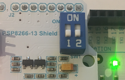
So, let’s take a closer look to the switches on the board. When both switches are in the “ON” position means that the TX0 and RX0 are connected to the VMA205. All messages send and received over the USB cable connected to the VMA101 are also received by the VMA205 and vice versa. Data send by the VMA205 on Serial are send to the VMA101.
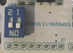
When in the “OFF” position the board is basically isolated from the TX0 and RX0.
So when flashing the VMA101 the switches need to be in the “OFF” position otherwise the both boards are receiving information causing the flash of the VMA101 to fail.
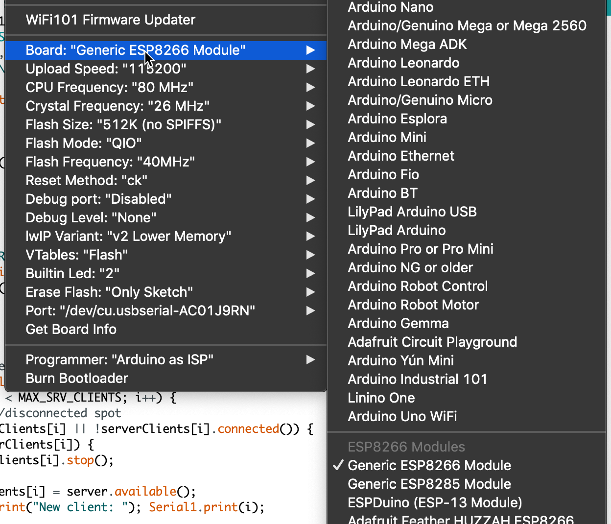
Now how to flash the VMA205 using the application “Arduino” to make it do something. Well the conclusion is: It can’t be done using the serial connection of the VMA101! An additional serial is needed in the form of a VMA440 to flash it.
Same procedure as described to flash it with new firmware. Connect everything, set the switches to ON and push the KEY and RST combination and start flashing from the Arduino app. Make sure to select the ESP8266 and the correct serial.