VMA101 with a VMA205 - warning: espcomm_sync failed

Recently i expanded the VMA101 with an VMA205 whereas i have issues with programming when the daughterboard is connected onto the VMA101.

Error codes in the IDE are:

Sketch uses 251972 bytes (50%) of program storage space. Maximum is 499696 bytes.

Global variables use 28052 bytes (34%) of dynamic memory, leaving 53868 bytes for local variables. Maximum is 81920 bytes.

warning: espcomm_sync failed

error: espcomm_open failed

error: espcomm_upload_mem failed

error: espcomm_upload_mem failed

In the manual it states that the switch 1 should be off before programming and turned on afterwards. These instructions i follow without any result.

Settings in the IDE are as following:

Reading various blogs it seems this to be a common issue with the wireless modules whereas resolution to the error is hard to find. As these products are purpose build to interface with each other the wiring is automatically correct though some step is missed.

Anyone have this error before?

Some updates; While using the WiFi.h and calling the status of the wifi module it always returns with the message WL_NO_SHIELD : assigned when no WiFi shield is present;

Also the status led of the shield is RED;

Turning of the TX and RX with the 2 switches allows the Arduino to be flashed though till now luck to get anything out of it.

After wiring the ESP6288 with power and the TX/RX to S1 sending all in- output to S0 i got some data (baud 74880):

ets Jan 8 2013,rst cause:2, boot mode:(3,7)

_load 0x40100000, len 2408, room 16 _
tXZ ⸮j
chksum 0xe5
_load 0x3ffe8000, len 776, room 0 _
tail 8
chksum 0x84
_load 0x3ffe8310, len 632, room 0 _
tail 8
chksum 0xd8
csum 0xd8

2nd boot version : 1.6
_ SPI Speed : 40MHz_
_ SPI Mode : DIO_
_ SPI Flash Size & Map: 16Mbit(512KB+512KB)_
jump to run user1 @ 1000

G⸮5Q32C Alrady Qio Mode
rf cal sector: 507
rf[112] : 00
rf[113] : 00
rf[114] : 01

SDK ver: 2.0.0(6ccde98) compiled @ Oct 28 2016 11:28:36
phy ver: 1055, pp ver: 10.2

Also while keep pressing the ‘KEY’ then press and release 'Reset" the messages changes:

ets Jan 8 2013,rst cause:2, boot mode:(1,7)

Though still not able to flash the device, communicate with it using the Mega board etc… Also no WiFi signal is received.

When reading the output at 115200 baud the system sends: “Ready” ← whatever that might mean.

Hopefully someone has experience with these boards…

So after the weekend still nothing useful. Started wiring up the device with a 5 volt power source using the UART connection on top of the Shield and connect it via an MAX232A onto an USB->Serial cable. Output of the shield is similar to the previous post and no progress is made reviving it.

Waiting for the ARD-A000059 to come in which is an USB to FTDI converter (basically an USB->RS-232->MAX232 on a single board). Hopefully that helps as some posts suggest to use such as setup.

Thursday i hope the board is available at our local hardware store (needed to be ordered) so i can continue development.

Thus far all the coding is done for the VMA101 combined with VMA311+VMA400+VMA203. using the MAX232A i was able to send data to the Arduino. Though without the wireless it is of no use to continue…

Last update - when “ready” is received and sending commands like ‘AT+GMR’ results in “ERROR” for every command send… What could be the problem…?

Hi,

It seems that you solve VMA205 espcomm problems…

Did You?

Thanks,

Hello XPA,

yes, the problem is resolved. Actually the manual is not that great and online it is not 100% matching with the boards that Velleman produces. So for those that struggled with flashing the VMA205 here is a brief tutorial on how to:

Prerequisites:

  • VMA101 Arduino Mega
  • VMA205 ESP8266-13 Shield
  • VMA440 FT232 to TTL
  • 4 Male to Female leads
  • micro USB cable
  • USB cable

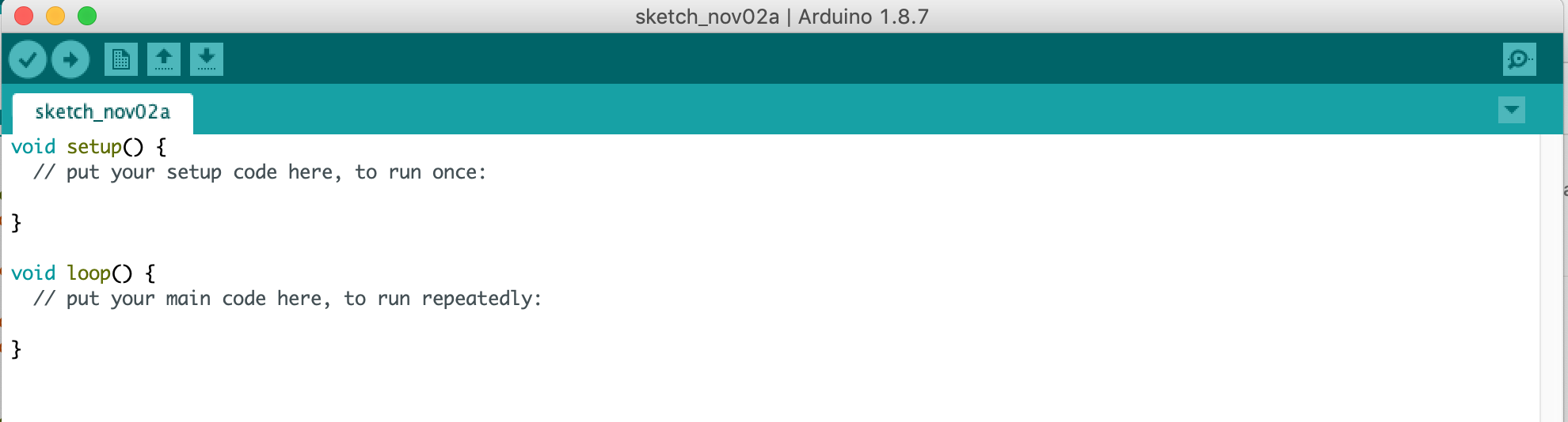
Step 1: Wipe the Arduino clean

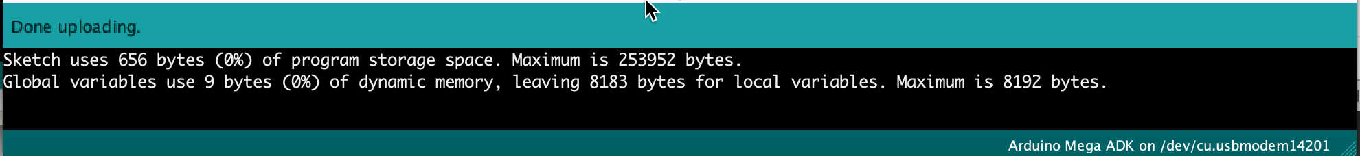
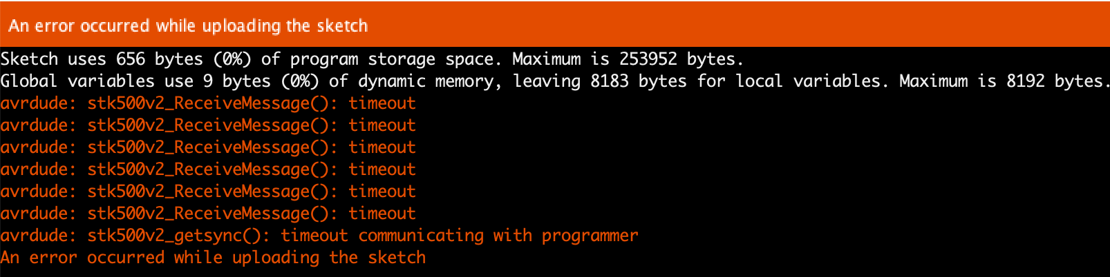
When you are flashing the VMA205 you shouldn’t have any serial communication or code running on your Arduino. It causes the flash process to fail for sure. So the first step is connect only the Arduino to you system and start a new project with nothing in it.

Push that to your Arduino. Now the system is clean and ready to start preparing for flashing the VMA205.

To confirm that cleaning the Arduino was correct you should see only 9 Bytes being written.

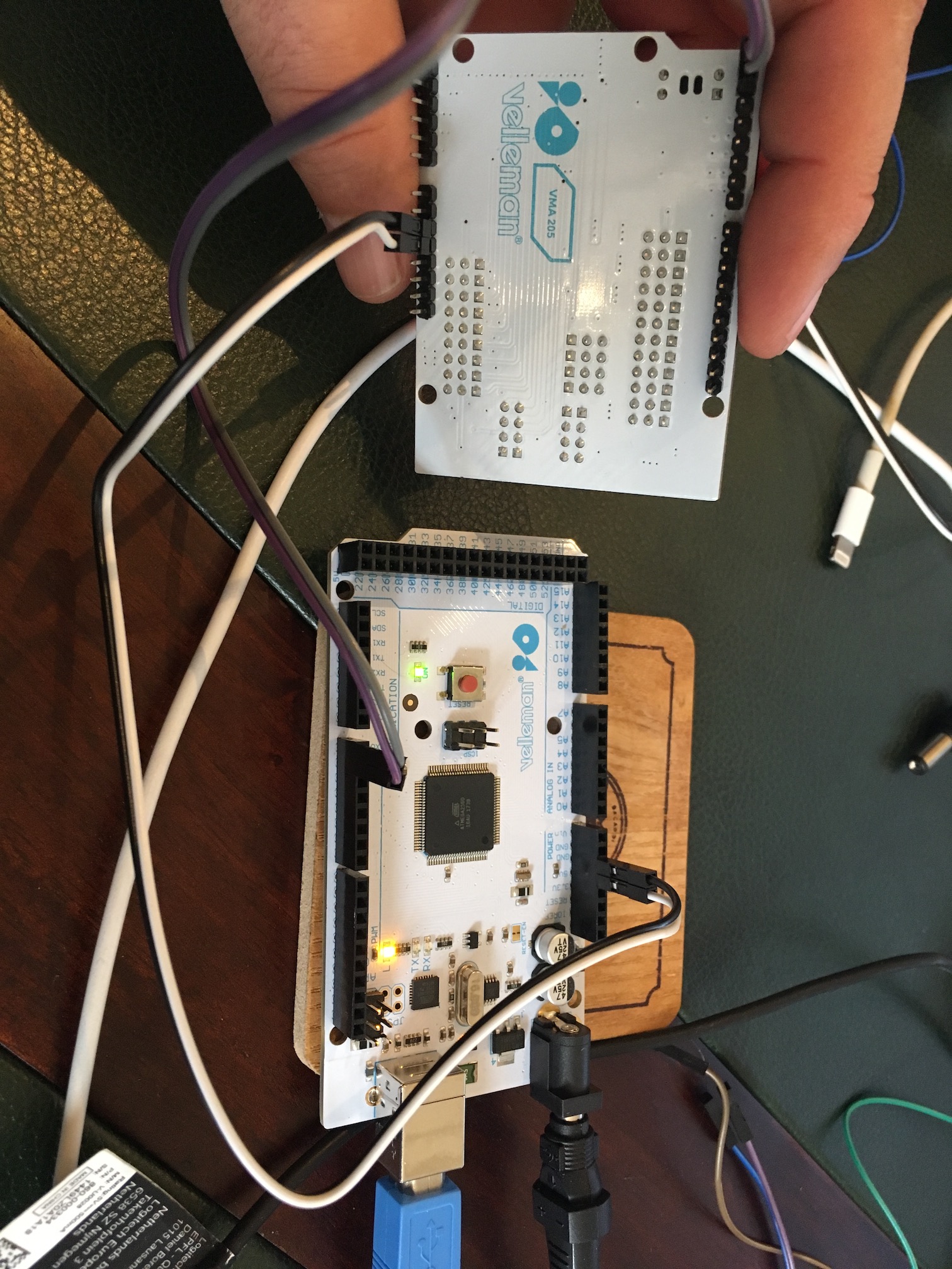
Step 2: Attach the VMA205 to the VMA101

Now before we do this, make sure that you have unplugged the USB cable from your device. Now connect the expansion board to the Arduino.

40

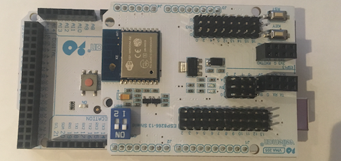
Beware that the pins on one side are not 100% aligned. The board fits even if you connect it wrong though you might damage the circuit as the ground, 5v and 3.3v would be incorrectly connected.

53

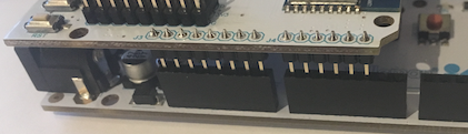
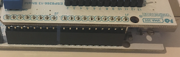
The other side aligns perfectly:

20

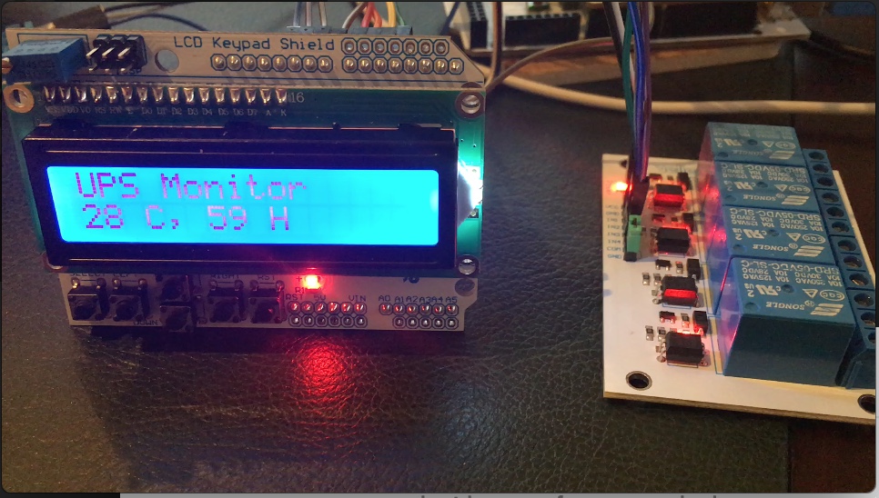
Step 3: Connect the VMA440 to the VMA205 UART

Flashing the VMA205 requires an VMA440 interface to be connected to the UART port on top of the VMA205. For some reason i was never successful flashing the VMA205 using the serial interface off the VMA101 (Arduino Mega).

Connect the TX, RX, 5V and ground to the UART port on VMA205.

01

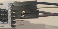
For some reason i tend to ensure color coding for the gnd and 5v are always the same:

  • Gnd = Black
  • 5v = white

Step 4: Connect the VMA440 to the PC and set the switches

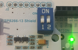
At this point you are ready to start the flash process. Don’t connect the Arduino VMA101 to your compute! only connect the VMA440 to the USB of your computer and this board will deliver power to rest of the components. Great! at this point you should see a blue light on the VMA440 and all the standard lights on the 205 and 101.

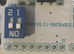
Final step is to check that the switches are in the correct position. Both of them need to be in the ON position.

22

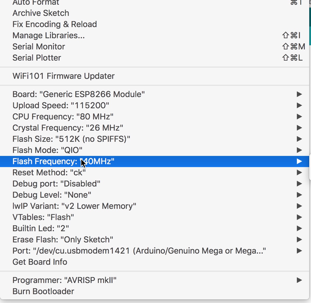
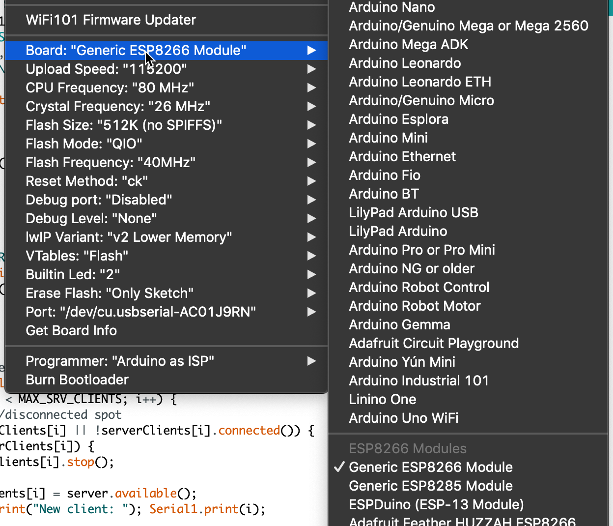
Step 5: Open the flash tools and ensure the board is in flash mode

Once you connected everything, switches are in the correct position and the system is powered on and the COM port is discovered you are ready to start the flash process.

Before you can flash the board need to be set into flash mode which is done using the RST and KEY switches. Press the RST (AND KEEP PRESSED) followed by the KEY button (AND KEEP PRESSED). Now release the RST button followed by the KEY button.

20

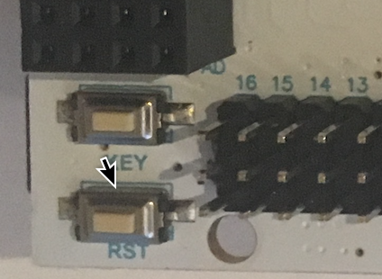
Your flash tool should at this moment recognize the VAM205 and start the flash procedure.

– GREAT YOU DONE IT! –

Personally i like to use a windows machine for this process using the tool ESP8266Flasher. How to go from here is another story…

Second part of the story is about; How did the initial flashing of the VMA205 resolved the issue where the error messages received are?:

error: espcomm_open failed
error: espcomm_upload_mem failed

So, let’s take a closer look to the switches on the board. When both switches are in the “ON” position means that the TX0 and RX0 are connected to the VMA205. All messages send and received over the USB cable connected to the VMA101 are also received by the VMA205 and vice versa. Data send by the VMA205 on Serial are send to the VMA101.

22

When in the “OFF” position the board is basically isolated from the TX0 and RX0.

59

So when flashing the VMA101 the switches need to be in the “OFF” position otherwise the both boards are receiving information causing the flash of the VMA101 to fail.

Now how to flash the VMA205 using the application “Arduino” to make it do something. Well the conclusion is: It can’t be done using the serial connection of the VMA101! An additional serial is needed in the form of a VMA440 to flash it.

Same procedure as described to flash it with new firmware. Connect everything, set the switches to ON and push the KEY and RST combination and start flashing from the Arduino app. Make sure to select the ESP8266 and the correct serial.

I know it’s an old thread but have any of you been able to make it work ?

What with the latest library ?

I only get “ready” by inverting tx and rx between arduino and esp is it how it works ? will i be able to work directly on a arduino with rx tx inverted ?

Thank you by advance

J’ai acheté un shield VMA205 pour mon Arduino en espérant programmer des connexions WIFI simplement… Je suis surpris de constater la pauvreté de la documentation de programmation de cette carte.

Le programme esp8266_TCP-Server.ino fonctionne mais ne donne le choix qu’entre TCPUDPDbg.exe ou de commandes AT pour échanger depuis la carte Arduino . Si s’est le cas, cette carte ne m’est d’aucune utilité !

Y a-t-il d’autres moyen de faire travailler la carte (WIFI client ou WIFI serveur) avec une bibliothéque déjà écrite pour l’EDI Arduino?

Dans quel cas utiliser un VMA440 ?

Merci pour vos réponses.

C.B.