Best to use analog output.
Take NPN transistor.
Connect the analog output to the base.
Connect the collector to an external +5V power supply.
Connect the motor between the emitter and GND of the K8055.
Connect the minus pole of the external power supply also to the GND of the K8055.
Can you explain why it is better to use analog output ?
I need 3 outputs for my project : two have to be used with PWM (they control two DC motors) and the other is just a switch (on/off) to let the current in a resistance or not.
Since there are only two analog outputs on the board, I need to use at least a digital one. Will it be OK ?
Another question : I used to use a board with roughly similar functionalities (µchameleon) but it seems to have passed out for no reason. With this board, the motor was connected between the external (+) (power supply) and the collector. The emitter was directly connected to the GND (as for the (-) of the power supply)
Is there a real difference with connecting the motor after the emitter ?
OK, you can connect the motors between the PWM outputs and the (+) pole of the external power. This way you do not need to add external transistors.
For the (on/off) switch you can use the digital output. Connect the resistor between the output and the (+) of the external power.
Please not: If you drive inductive loads (relay coil) instead of the resistor you have to connect the (+) of the external power supply to the CLAMP terminal of the K8055. This damps the switching voltage spikes of the coil.
Thanks for the answer and for the tip (I probably won’t use any coil)
When you say “you can connect the motors between the PWM outputs and the (+) pole of the external power”, this means that the current/voltage of the external power supply is going through the circuit. Isn’t it a problem if I use voltages such as 12V ?
Indeed I still use a Mosfet with the PWM so as to isolate the board from the external circuit…
You can connect external voltage up to 40V. The maximum current to the PWM output must be limited to 100mA.
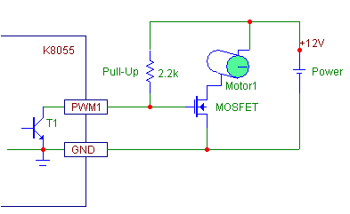
You may also use your external MOSFET but in that case you must add a pull-up resistor (about 1k to 5 k ohms) from the PWM output to (+) of the power supply.
Please note: When selecting the MOSFET, make sure that the specified maximum gate-to-source voltage is over 12V. - Otherwise the MOSFET will be broken if you use this connection as is.
Put the motor between the Drain and +12V as illustrated in the drawing.
This way you get higher driving voltage to the motor.
It may be good idea to add a clamping diode over the motor (cathode to +12V).