Hello to all, in case someone reads 
So we purchased 4 VM100, the factory pre-assembled version of K8060.
Including original Velleman toroidal transformers.
Subsequent assembly was carried out in a professional workshop by experienced technicians with forced cooling fan and fully grounded aluminium enclosure.
The first still behaves like a charm and is used in the frame of scientific research as instrumentation amplifier.
Second one burst in flames shortly after power-up, meaning maybe 20 seconds. Aftermath showed a probably poor thermal connection between one transistor and the heatsink. No bias was adjusted since the operator manual specifies that the module is adjusted (and therefore implicitly) powered-up at the factory. So a warranty claim was filed to the distributor.
Third and fourth of absolutely identically assembled devices are unusable for the following reason:
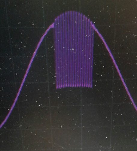
-The output is HIGHLY DISTORTED After the input (fed by a Tektronix function generator) reaches about 200mV Peak-To Peak on a pure sine wave @ 150 to 300 Hz.
We took oscillograms. All is fine below approx. 200mVpp at the inpout then, as we slowly approach the critical threshold, negative sharp spikes progressively appear on the first half period, shortly after the sinus wave starts to decrease from it’s maximal output value of about 6 Vpeak.
At power up, with the input left open or shorted with a 50 Ohms BNC cap, the output will go haywire for a moment, violently swinging at higher frequencies between V- and V+ for a few seconds. Then it’ll stabilize within reasonable limits to ground.
On occasion the primary fuse, 1A slow burn will blow at powerup.
We measured the primary current using a Textronix hall effect current sensing clamp and found a highly non-sinusoidal behavior with very sharp spikes, rising up to 600mApp on a idling device.
Transformers behave as if badly saturating even at idle at this point of the investigation.
Same picture on the secondaries. Sharp spikes of meaningless peak to peak current values well synchronized with the commutation points of the rectifier diodes. Remember, there’s no input at all connected for this test, device is IDLE.
We checked of course the secondaries phase, and symmetry, all matches within the usual couple of percent of amplitude difference between the secondaries.
Voltage exhibits a better, close enough to sine wave signal.
Further we placed a series of chokes on the primary and could smoothen a bit the current spikes enabling us to operate one device till about 240mVpp sine wave on it’s input @ 150Hz.
Yet on powerup, without signal or with a 50 Ohm BNC cap, with or without any, including pure resistive 5 Ohms load, the output will go haywire for a second or so, blowing the 1 A slow fuse on the primary in most cases.
What re we facing here ? A vicious transformer malfunction, airgap in the magnetic circuit ?
The current oscillograms trend to show that the magnetic circuit behaves as being extremely saturated, unable to cope with even it’s own idle current.
Now, this is VERY BAD since equipment is delayed by mire than one week and we need it to perform ASAP.
Can someone help, is there a support for these products ? I personally phoned in Belgium. No service other than this forum, officially said, evidence available on request.
Thanks, let’s see where this will lead ? We of course won’t alter the remaining VM100 modules unless specifically instructed to do so. We both them as ready to use modules under warranty.
Best regards, thanks for the attention,
“Kiki”


