Hello @TMToronto,
We have checked the manual and your complaint about the WPM333 / TB6560 driver.
The manual is correct, all functions are working.
Maybe a wiring problem in function of the Masso G3. You can take best contact with Masso G3 support
Depending on what you’re describing here “see quote below”, I think it’s a wiring problem, or not all grounds, or EN - / + pins are connected correctly.
the odd behaviour is that the stepper motor will move on its own without any DIR+ or STEP+ signal generated by the Masso G3.>
This can be the result that the EN+ pin is not connected (floating).
Or if EN- and EN+ are disconneted, this means that the Enable pin is always at LOW level and the thriver is enabled.
So check your connections and try this example sketch via Arduino first to check if the WPM333 are working. If this is working correctly, then you can check with Masso G3 or you can contact Masso G3 support.
/*
@@@@@@@@@@@@@@@@@@@@@@
@@@@@@@@@@@@@@@@@@@@@@ @@@. @@@ @@@. @@@@ @@@@ @@@@@@@@@ @@@@@@@@@@@@@. .@@@@@@@@@@@@@ @@@@@@@@@
@@@@@%%@@@%%@@@%%@@@@@ @@@@ @@@ @@@@ @@@@ @@@@ @@@@@@@@@@ @@@@@@@@@@@@@@ @@@@@@@@@@@@@@ @@@@@@@@@
@@@@@ @@@ @@@ @@@@@ @@@@ @@@ @@@@ @@@@ @@@@ @@@@ @@@@ @@@@@ @@@@@ @@@@@ @@@@ @@@@ @@@@
@@@@@ @@@@@ @@@@ @@@@ @@@@ @@@@@@@@@@@@ @@@@ @@@@ @@@@@ @@@@@ @@@@@ @@@@ @@@@ @@@@
@@@@@ @ @ @@@@@ @@@@ @@@@ @@@@ @@@@@@@@@@@@ @@@@@@@@@@@ @@@@@ @@@@@ @@@@@ @@@@ @@@@@@@@@@@
@@@@@ @@@@@ @@@@###@@@@@##@@@@@ @@@@ @@@@ @@@@@@@@@@@@ #@@@@@###@@@@@ ##@@@@@###@@@@ @@@@@@@@@@@
@@@@@@@@@@@@@@@@@@@@@@ @@@@@@@@@@@@@@@@@@@ @@@@ @@@@ @@@@ @@@@@ @@@@@@@@@@@@@@ @@@@@@@@@@@@@@ @@@@ @@@@
@@@@@@@@@@@@@@@@@@@@@@
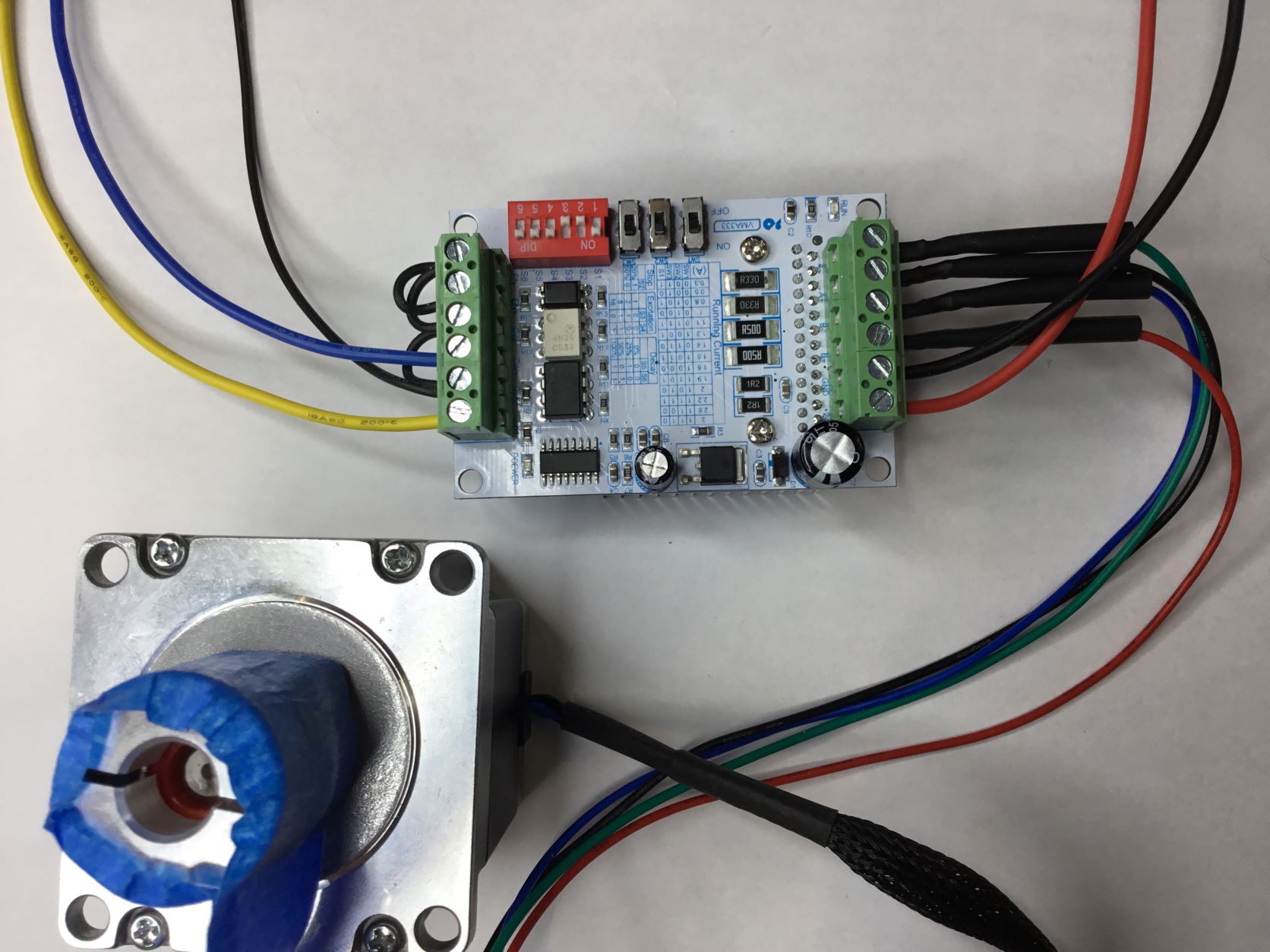
This Whadda WPM33 module is stepper motor driver controller.
The controllor board uses the TB6560AHQ microstepper driver chip from Toshiba.
It can be used to drive two-phase bipolar stepper motors.
The Driver is easy to use, and can control large stepper motors like a 3A NEMA23
Datasheet of TB6560AHQ: https://www.velleman.eu/downloads/29/infosheets/tb6560ahq_datasheet.pdf
Pinout & function descprition of WPM333 / VMA333: https://www.velleman.eu/downloads/29/infosheets/tb6560_connection.pdf
The chip has several safety functions built-in like over-current, under-voltage shutdown, and overheating protection.
However, it does not have reverse-voltage protection, so make sure that you connect the power supply correctly.
You can find more specifications in the table below.
This example code allows you to control a stepper motor with Arduino and without a library.
For more information about the Whadda Stepper controller board, consult the manual at the WPM333 product page on:
https://whadda.com/product/tb6560-3a-stepper-motor-driver-board-wpm333/
Specifications:
------
Operating voltage: 10 – 35 VDC, 24 VDC recommended
Max output current: 3 A per phase, 3.5 A peak
Microstep resolution: full, 1/2, 1/8 and 1/16
Protection: Low-voltage shutdown, overheating and over-current protection
Pin connections:
***************
VCC 10-35V (24 VDC recommended)
GND Power supply ground
EN- Arduino GND
EN+ Arduino PIN 8
CW- Arduino GND
CW+ Arduino PIN 2
CLK- Arduino GND
CLK+ Arduino Pin 5
A- | A+ Coil 1 Stepper motor
B- | B+ Coil 2 Stepper motor
Note:
-----
If the Enable pins (EN- and EN+) are disconnected.
This means that the enable pin is always LOW and the driver is always enabled.
Current Settings in function of stepper motor:
----------------------------------------------
You can adjust the current that goes to the motor when it is running by setting the dip switches SW1, SW2, SW3, and S1 ==> on or off.
It's recommended to start with a current level of 1 A. If your motor is missing steps or stalling,
you can always increase the current level later. Or check the datasheet of stepper motor you are using.
To set the switches in function of the current, see the "Runninf Current" table, metioned in this PDF sheet:
https://www.velleman.eu/downloads/29/infosheets/tb6560_connection.pdf
*/
// defines pins numbers
#define dirPin 2 // CW+
#define stepPin 5 // CLK+
#define enPin 8 // EN+
// define the steps per revolution
#define stepsPerRevolution 2000
void setup() {
pinMode(stepPin, OUTPUT);
pinMode(dirPin, OUTPUT);
pinMode(enPin,OUTPUT);
digitalWrite(enPin,LOW); // Enable the Driver
}
void loop() {
// Set the spinning direction clockwise:
digitalWrite(dirPin, HIGH);
// Spin the stepper motor 1 revolution slowly:
for (int i = 0; i < stepsPerRevolution; i++) {
// These four lines result in 1 step:
digitalWrite(stepPin, HIGH);
delayMicroseconds(2000);
digitalWrite(stepPin, LOW);
delayMicroseconds(2000);
}
delay(1000);
// Set the spinning direction counterclockwise:
digitalWrite(dirPin, LOW);
// Spin the stepper motor 1 revolution quickly:
for (int i = 0; i < stepsPerRevolution; i++) {
// These four lines result in 1 step:
digitalWrite(stepPin, HIGH);
delayMicroseconds(1000);
digitalWrite(stepPin, LOW);
delayMicroseconds(1000);
}
delay(1000);
// Set the spinning direction clockwise:
digitalWrite(dirPin, HIGH);
// Spin the stepper motor 5 revolutions fast:
for (int i = 0; i < 5 * stepsPerRevolution; i++) {
// These four lines result in 1 step:
digitalWrite(stepPin, HIGH);
delayMicroseconds(500);
digitalWrite(stepPin, LOW);
delayMicroseconds(500);
}
delay(1000);
// Set the spinning direction counterclockwise:
digitalWrite(dirPin, LOW);
// Spin the stepper motor 5 revolutions fast:
for (int i = 0; i < 5 * stepsPerRevolution; i++) {
// These four lines result in 1 step:
digitalWrite(stepPin, HIGH);
delayMicroseconds(500);
digitalWrite(stepPin, LOW);
delayMicroseconds(500);
}
delay(1000);
}
Hope this will help you further,
Best Regards,
Velleman Technical Support