Thermocouple-k upgrade

Hi!

I recently got my 2 thermocouple-k amplifier adapters delivered. (Analog K-Type Thermocouple Amplifier - AD8495 Breakout) LINK
I wat touse them on the heatbed for more precise temp readings, and especially on the hotend, for getting higher temp range and mor precision.

The amplifier boards put out a voltage ov 1.0V per 100°C so i can easily go up to 400°C range for printing higher temp materials like nylon.
Also i will get mor precise temp readings as the thermocouple will be far more accurate than the usual thermistors, especially above 250°C.

What i know by now, is that i have to connect the amplifier outputs to some ADC on the main controller.
There are 2 Options for doing that.

  1. is desoldering the resistor/capacitor couple from the pcb and connect the output directly to the chip input.
    (not my favourite cause i want to change as little as possible on the board)

  2. is soldering the output line to one of the 2 leftover but unwired ADC ports on the chip.
    (i think i will try that first, cause today my hot-air soldering station arrived)

What i don’t completely understand is, how the thermistor tables in marlin are built. (what does the oversample value mean exactly)
Can someone point me out with that?

If someone can help me with reassigning the pins in marlin, so the firmware can use the leftover ADC ports for temp sensing
that would also be great.

Anyway, i will try to figure that out by myself too, but any hint is appreciated.

Oversampling is just mean averaging for better resolution.

The tables multiply the basic values by the number of samples. It saves having to divide by the number of samples.

With a linear input, you won’t need the averaging as much. I’d probably go with a three sample rolling average.

[quote=“Paul Compton”]Oversampling is just mean averaging for better resolution.

The tables multiply the basic values by the number of samples. It saves having to divide by the number of samples.

With a linear input, you won’t need the averaging as much. I’d probably go with a three sample rolling average.[/quote]

Thanks for your reply Paul.

I already know what oversampling actually is.
I just didn’t get how that numbers in the Thermistor tables are calculated.
I want to make a new table from scratch, so i think i will need to find new values for these.

Do you know where the pins for the ADC’s are defined in marlin?
I’m currently lost there. I simply cant find the place.

cheers,

Christian

[quote=“ichbinsnur”]
Do you know where the pins for the ADC’s are defined in marlin?
I’m currently lost there. I simply cant find the place.

cheers,

Christian[/quote]

I just found it in pins.h.
What i’m not exactly sure about is the numbers for the pins.
Are they taken directly from the pinout of the chip?

#define TEMP_0_PIN 13 // ANALOG NUMBERING #define TEMP_0_PIN 15 // ANALOG NUMBERING #define TEMP_1_PIN -1 // ANALOG NUMBERING #define HEATER_BED_PIN 9 // BED #define TEMP_BED_PIN 14 // ANALOG NUMBERING

And why does the firmware define 3 temp inputs?
The 3drag board actually has only 2.
Does it use TEMP_1_PIN/TEMP_2_PIN
or TEMP_BED_PIN for the bed?

I currently have a print running, so i can’t disconnect the printer to look at the board.

I just found that the pin numbers are taken from the arduino pinout mapping sheet.
What else … :wink:

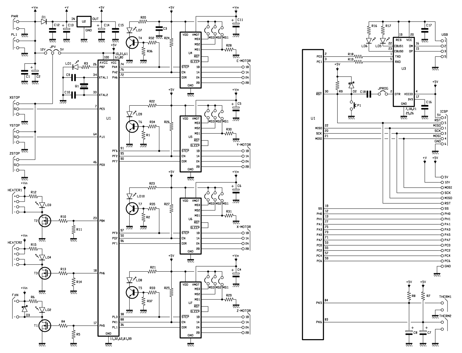
If i get the schematic right,
arduino pin 13 and 14 are used for the temp sensors.

so

// PIN 84 - PK5 - (ADC13/PCINT21) - Analog Pin 13
// PIN 83 - PK6 - (ADC14/PCINT22) - Analog Pin 14

will equal to

  #define TEMP_0_PIN         13   // ANALOG NUMBERING  - Extruder temp
  #define TEMP_1_PIN         15   // ANALOG NUMBERING - Whatever temp?
  #define TEMP_2_PIN         -1   // ANALOG NUMBERING
  #define HEATER_BED_PIN     9    // BED
  #define TEMP_BED_PIN       14   // ANALOG NUMBERING - Heatbed temp

Thus i believe the pins

// 87 - PK2 - (ADC10/PCINT18) - Analog Pin 10
// 86 - PK3 - (ADC11/PCINT19) - Analog Pin 11
// 85 - PK4 - (ADC12/PCINT20) - Analog Pin 12
// 82 - PK7 - (ADC15/PCINT23) - Analog Pin 15

are free to use.

Can anyone confirm this? Maybe Velleman?

Hey, currently i am also looking into a lot of customization of the hard- and software.

But as far as I know you can not access the PKx Pins that you wanted to use. I do not see where they would be accessible.

But the ATMEGA 2560 that is used here hast more ADC Pins. just google for the Datasheet and then you can check wich of the free and accessible Pins have ADC.

Best regards,

Niklas

Thanks for your reply Niklas.

As i figured out from the schematics the pins i mentioned are the only ones free for ADC conversion.
All other pins are already used utherwise.
The Analig 13 and 15 connect to the stock thermistor connectors.
So the other 2 are left over.

Only bad thing is, they are not broken out on the pcb.
So if i want to use them i would have to directly tap the ATmega pins on the chip.
I’ll try to do that (got my new hotair station yesterday), but first i hav to figure out how to
get the firmware to use those 2 “spare” pins for reading the temp.

By the way, my hotair solder station turned out quite handy in “repair welding” cracked layers… :wink:

Hello,

i just had a look at the schematics and pin setup of the Atmega 2560 and it does seem that these Pins are the only ones for ADC. Too bad…

Soldering directly at the Atmega is quiet tricky and if there is any other way i wouldn’t recommend it…

But so far the only idea that came to my mind would be a lot more work. You would have to use a second Arduino and transmit the temperature using the Second Rs232 Pins of the Atmega. And that might just be a bit too much effort for the effect.

Accessing the spare Pins should just work like you thought. the software refers to the AnalogPins using their Number (i.e. 0 to 15) and not the overall pin number.

Do you want to use your temp sensors instead of the original ones or as spare ones?

If you want to replace the original ones you could access the already broken out pins somewhere else besides directly at the Atmega.
(somewhere at the Resistor?)

If you want to use them as spare sensors do you already know how the firmware implements the Sensors 1 and 2?

Greetings

Well, i already thought about connecting the amplifiers to the stock heater pins, but that would mean
i have to unsloder the caps and the resistors.
I want to avoid that if possible. I wnat to make the less possible changes to the Board.
I also want to keep the LCD connectable, so i can’t use any of the broken out pins.

I think i’ll try to use the 2 free analog pins, even if that means to tap the IC directly.
(should be manageable with a hotair reflow solder station)

I didn’t dive into marlin that deep yet that i completely know how the temp routines work.
If you can support me with that i would be glad.

cheers,

Christian

Hi Chistian,

Hmm, seems that we are a bit on the same track…
As I have been looking into the thermocouple as well.

With marlin you have a couple of options (you might already know about them) (in both cases you do not need to modify any thermistor tables just change a define).
You can select an analog interface, using an AD (analog devices) Thermocouple interface chip which provides a linear voltage output/degree, and connect this to an ADC pin of the MEGA.
Or you can use an SPI interface, MAXIM thermocouple interface with onchip ADC and SPI.

With the default K8200 controller the SPI will mean that you have to sacrifice something if you want to use the standard IO pins.
The Analog version should be connectable, to the thermistor input.
Unfortunately the R and C values are not given, but they just provide a bias / filter option.
Just looked at the AD8494 datasheet and see that it has an opamp output, capable of driving 7mA…
As the thermistors are 100k, I do not expect the R to be very low ohmic as it would have no meaning for the ADC.
The C capacitance could be an issue if its is very large (>10uF), but would doubt it as it would interfere with the thermistor.
I would say that leaving the R and C would not affect your thermocouple output to much, other than provide additional filtering.
You can insert 1K in series with your AD8494 and the K8200 thermistor input too protect it, besides adding to the RC filtering, It should not interfere.
Measure the voltage over the 1K resistor to see if there is anything to worry about before removing it (voltage should be mV).
This way you do not have to remove any components.

Personally I have ordered a arduino MEGA2560 and RAMPS 1.4 to have more control, and am planning to connect the thermocouple with an ADxxx to the analog input as well.

Soldering on the ATMEGA is not for the faint harted, and hot air is excellent for chip de/soldering but you will need a very very small tipped iron and extreemly steady hands to solder on the pins.

Best Regards,

Robin

Hey, thanks Robin.

Yes,i already knew thear are some options in Marlin for themocouple connection.
But AFAIK (didn’t recheck recently) the Analog version relies on a different amplifier chip with different gain.
So i’m not sure if that will work.
EDIT: I just found the datasheet and the AD595 supported by marlin has a rating on 10mv/°C.
(maybe the algorythm for the AD595 can be changed in the firmware to fit the 5mV/°C i need for my amplifier)

At first i thought about the SPI solution too, but i think it will interfere with a connected LCD controller.
So i put that aside for the moment.

The resistors on the THERM lines are 4.7 k Ohms and connec the signal ine to GND, thus making
a voltage divider out of the thermistor and on board resistor.
The cap is only there to stabilize the whole thing a bit, to prevent it from resonating, i think.

As the output of the amplifier board is 1.25v + n*5mv per degree i don’t think it will get good
results, but i think i’ll just give it a go and look what comes out in the end.
I didn’t do the math yet, so it might prove me wrong there…

For the future i plan to go for a duet (arm powered) controller.
There is an expansion board for it with which you can run 8 steppers and 6 heater/thermistor pairs in total.
Quite amazing i think. I just don’t know which firmware will run on it.
Marlin isn’t ported for the duet yet AFAIK.

regards,

Christian

p.s. :

Who says i’m faint hearted? ;D
Well i think with solder paste and thin wires it shold be doable.

Guess that its just an equation (but did not check the firmware for it).
It seems that my Thermistor got jalous about me talking about thermocouples as it went belly up on me tonight ; (…

On the K8200 there are no free pins to do so, so you will either have to sacrifice your SD or LCD…

The resistors in the schematic are pullups.
And indeed make a (100k/4k7 + 100k) voltage divider for the THERM.
A 4k7 pullup on a opamp output should not be an issue, as the output can supply enough current to drive it to the desired level.

The cap is just part of an RC filter to remove the noise on the input (hardware avering), no more no less.

Do the math or test, think that it will work.

I have some experience with SMD and wire soldering, so I speak out of experience, and IMHO, the MEGA is a bridge to far…
Be aware with solder paste as you have a serious risk of shorting, especially when stray thin balls form…
I would suggest 0.1mm wire or thinner.

Let me know your results…

Thanks again Robin.

I’ll hook the thing up to the THERM Port directly tomorrow morning and post back how it turns out.

The AD8495 has a reasonably low output impedance, so you might well get away with driving the old thermistor inputs without modification.

I just reconsidered the whole thing.
Seems i was a bit tired yesterday. :wink:

The Pullup resistor drives the sensing line to about 4.8V, thus making any reading from the amplifier totally impossible.
The amplifier delivers 1.25V at 0°C + 5mV per degree. So it simply can’t work without unsoldering the 4.7k resistor.

I believe the voltage on the input of the amplifier would also kill the chip, because it’s not designed for such reverse Voltage.

But as Paul wrote it “might” work i will try it out anyway, as i have one amplifier in spare. :wink:

Okay, i did it.
I hooked up the output of my AD8495 to the THERM port without changes.
(i had the Breakout battery powered just for testing)

And … it worked!

Thank you Paul and Robin for pointing me the right way.
I didn’t believe it would be that simple. (i’m still learing about electronics in my fee time)

So i made a new Thermistor table, calculating the voltage offset given by the amplifier to ADC values.
I assumed 5V to correspond to the max 1023 value of the ADC.
Looks quite good. The commented values (in the thermistor table below) represent the values i got from my thermocouple equipped meter.
Although it might be the connector of my meters thermocouple is bad, as i found if i connect the second themocouple i bought directly
to the meter (without plug) i get readings almost exactly 4°C lower than repetier shows with my calculated thermistor table.

So it seems to be quite accurate right from the start. :))
The temperature reading is now quite linear and stable over the wole range and reacts quite fast.
Way faster than with the thermistor before. It swings around target about 1°c max now.
With the thermistor it drifted up and down around 3°c and up to 6°C sometimes.
Especially in the higher temp ranges.

So again, big thanks to Paul and Robin!

Here is the Thermistor table i made :

#if (THERMISTORHEATER_0 == 70) || (THERMISTORHEATER_1 == 70) || (THERMISTORHEATER_2 == 70) || (THERMISTORBED == 70) // Adafruit AD 8495 Thermocouple-K amplifier Breakout connected to THEM port on k8200/3drag controller without removing 4.7k pullup and capacitor const short temptable_70[][2] PROGMEM = { {665*OVERSAMPLENR, 400}, {614*OVERSAMPLENR, 350}, {563*OVERSAMPLENR, 300}, //275 {512*OVERSAMPLENR, 250}, //228 {461*OVERSAMPLENR, 200}, //181 {409*OVERSAMPLENR, 150}, //135 {358*OVERSAMPLENR, 100}, //91 {307*OVERSAMPLENR, 50}, //45 {256*OVERSAMPLENR, 0}, }; #endif

So now i can print even Nylon without worrying about the thermistor accuracy and temp spec.

GREAT!

Hi Paul, how did you figure out that?

I didn’t find any impedance or resistance values for the Output in the datasheet.
I think my measurements are slightly off caused by the voltage divider created from the Output of the AD8495 Board and the pullup.
The differ quite a bit at the upper end of the temp scale. (about 25°C at 300°C checked with my multimeter thermocouple)
Can i find the resistance values somewhere? I want to correctly calculate the output voltage to get really precise temp redings.

And additionally, just for curiosity, how did you come up with your suggestion that connecting it “as is” would work?
From my understanding it simply “shouldn’t” work. :wink:

[quote=“ichbinsnur”]I didn’t find any impedance or resistance values for the Output in the datasheet.[/quote]It’s inferred. The output short circuit current is listed as 7mA with a 5v supply, so 5/0.007 = ~714ohm.

[quote]And additionally, just for curiosity, how did you come up with your suggestion that connecting it “as is” would work?
From my understanding it simply “shouldn’t” work. ;)[/quote]Simply that the Op-amp had enough output current to drive a 4K7 ohm load.

[quote=“Paul Compton”][quote=“ichbinsnur”]I didn’t find any impedance or resistance values for the Output in the datasheet.[/quote]It’s inferred. The output short circuit current is listed as 7mA with a 5v supply, so 5/0.007 = ~714ohm.

[quote]And additionally, just for curiosity, how did you come up with your suggestion that connecting it “as is” would work?
From my understanding it simply “shouldn’t” work. ;)[/quote]Simply that the Op-amp had enough output current to drive a 4K7 ohm load.[/quote]

Ah, now i understand.
But are you sure the ability to drive 7mA output current would be equal to the output port resistance?
I’m not quite sure.

But anyway, it works… :wink: