There is a problem with heat emission, especially if you want to print small parts (less than 20 x 20 mm) or horizontal surfaces with lots of details.
Then while printing a part of the surface remain under the printhead and melts or remelts there, not be cooled down by the ventilators.
With small parts (my slightest up now are 3 x 5 x 4 mm) my work-around is to print 2 parts at same time, arranged successive so if one layer is printed on one part, the other part is cooled sitting under one of the ventilators airstream meanwhile.
But with bigger parts, e.g. a spinner for an air-screw with a convergence at its top, you can’t print two every time.
I experimented with additional ventilators, it don’t becomes better distinctly. With standard print head(s) the distance between nozzle and head is very small, no much air to get there and also with other heads witch have more distance the effect is the same: the cooling of the printhead increases and the heat emission actually becomes stronger, cause the control-circuit wants to balance that with more electric energy.
And the heat emission is something like “invisible light”, not affected by air.
Cause i come from plastics-industry, we often have hot and cold parts nearby. Solution there is insulation.
I looked around but i can not found any insulated print head in the 3d-printers szene nor written anything about.
Does anybody have experience with that ?
My idea is to build a shoe from PCB-plate (Pertinax or Fiberglass) snapping over the printhead from bottom side, covering 5 planks. Only with 3 mm opening for the nozzle. Then also additional cooling makes more sense.
Has anybody another idea ?
p.s cause i was asked: i am not as rich as my namesake “Dagobert”, i only look same addlebrained ;-))
Well you could lift the head every layer if the time is shorter than a set amount of time. But it’s kinda by design flawed by having the nozzle just a few mms below the heater block… Pla has this effect immensely… Abs works better imho. Another type of print-head lowers this effect also…
I found this effect too, My experience can be summarised like that:
The impact of this effect is depending on the printed materials.
different PLA suppliers have different critical temperatures
The colour of the material is a key factor: darker materials are a better heat collector than light materials
(I found this effect for 3DK metallic blue filament, it never occurred on Velleman PLA white)
Since the radiation is following a squared law, even a small change in the distance can significantly reduce the induced heat.
I could nearly remove this effect when switching from 0.1mm layer thickness to 0.2 mm laxer thickness.
Nozzle temperature of the K8400 is generally higher than the shown temperature. Reduce the extrusion temperature to a value where still a good flow can be achived without slipping in the extruder. As a target the minimum extrusion temperature given for the material can be taken for the first attempt.
isn’t the “squared law” for radiation only valid if the source is a point ?
I think if the heat-source is an area, like our print-heads, the energy under the head, impacting to the printed plastic is the same whether it is 2 mm away or 30 mm away. The heat-radiation is parallel there.
Yes, going down with the printing-temperature reduces this effect, but brings other disadvantages, main thing: it reduces the toughness of my printed technical products i need often.
So i think the best solution is to do a thermal insulation of the print-head.
Only then you can make a good cooling. (this will also help with other problems i read around here)
Am i really the first who want this ? No other experiences ?
just want to tell i made my first tests with thermal insulated print-head.
Cork seems to stand 250 °C (tested with my soldering iron up to 270 °) and i shaped out a shoe from cork (from a sparkling wine bottle
First prints with an extra fan clamped provisionaly beside the print on the glassplate are looking very good now !
Unfortunately the cork is not dimensionally stable with some time, so the bottom of the shoe (wich could only be 2mm thick) sagged down and rubed against the print.
So i need another material for the insulation, a thermoset would be ideal (like “Bakelit”, standig hard for over 400 °C), but i live outside of civilization …
if you can get your hands on it, try Calciumsilicat felt. It is used in ~5cm wide 1mm thick strips in dental laboratories to line muffles used for casting metal. It withstands temperatures of >1000°C is non toxic, non cancerogenic (you can eat it). If removed after heating it will be a little brown from cellulose binder in the material, but the heat insulation properties are unchanged.
Only downside is that is has to be contained in a little aluminium shroud, because it’s to soft to stand on its own. I’m playing around with it right now with a shroud made out of 0.3mm aluminium with limited success as the shroud was just a square box so I had trouble getting cooling under there. Next will be wedge shaped.
very interesting material and information. And it is good to know not to be alone going this way with the printhead insulation. (o’ how theatric ;-))
But will be also very difficult for me to get it. (as a former german i live on a farm in the semi-dessert of South of Spain. i have problems to get a simple piece of brass here )
Cause i have done the programm for my small CNC-milling machine already for that, i favor some hard material at the moment wich i can mill. Perhaps i can find some at the scrap yard.
And you bring me to another idea, that is to use ceramic - compounds, once hardened they are good for over 600 °C. There must be a rest in my laboratory-chaos i brought here 10 years ago … (have to mill a mold then)
also very interresting, i should get this in a spare-part shop for cars ?
How do you use this ?, do you simply coat it on the print-head respectively on the heating-block ?
By the way: i ordered two “E3D-V6 All-metal 3D Printer Extrusion Head Nozzle With Fan” from banggood. You can get this replica for less than 16.- € each with delivery included to Europe ! Let us see what quality…(but i can help me out ;-))
I am not happy with the original one’s: no space above the head for good insulation and cooling, no simple change of nozzles (especially when printing with reenforced filament), no possibility to adjust height (different height of left to right nozzle)
Yes, heat resistant fluid slicone gasket can found in a spare-shop for cars. I coated the heating block with a thin layer. Even a thin layer is effective. I did also do a new temperature calibration i.e. a new temperature table for the firmware. The standard Vertex one was completly wrong. At last auto trimmed new regulator constants. Prints Now PLA @210C and ABS @245C “real” temperatures without any problem at all.
Very good idea ! and easy to do.
i think will do same, just waiting until i get my new print heads delivered and running.
Can you tell me more about your temperature calibration for the vertex, or where i can find more information about that please ?
(i know the ‘basics’, 30 years of practicing engineering and electronics, i am just new to 3d-printing ;-))
please be careful with a new calibration of the thermal sensor. With 30 years of practising electronics you may easily calculate the error voltage at the controller input due to wrong “temperature calibration”. The temperature calibration is given in lookup-Tables in the firmware, providing for the commonly used thermistors predefined reference. In the given operating condition the tolerances of the parts are so small, that they will responsible for 1°C error reading, depending on thermistor type.
I’m still convinced that the major reason for discrepancies in the temperature readout is the poor and unreproducible thermal coupling of the temperature sensor to the heater block. This is solved better for the e3d heater design. So with your new heater front-end you may have to select a different calibration curve for the shipped thermistor (and for shure a new calibration of the PID parameters).
my E3D-Clones are running now, working perfect and i didn’t have to change anything with the thermal sensors.
Hello Raby,
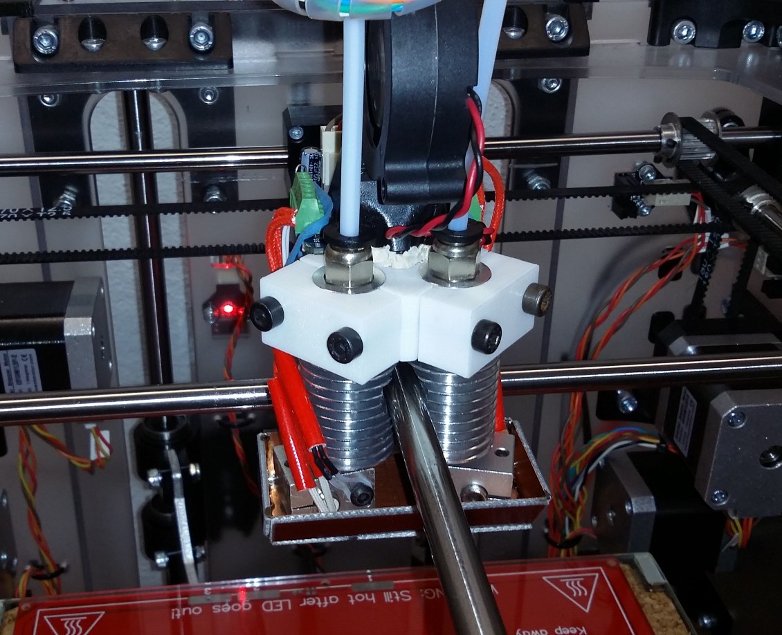
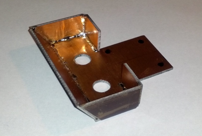
Having now more space between the nozzles and all other parts there, i welded some PCB with copper on one side together. Provisional for the first time , i needed a gear-box printed with lots of details, small axes, brackets etc. Without shield you only get sludge.
It is attached only with a rubber-ring at the moment, going from left terminal around under the xy-block to the other side up to the right terminal. This keeps also my cables close to the block. The stationary fan blows from front the cool air under the shield.
Later i want it made from thinner PCB and only a shoe, snapping over the heater-block …
Nice job.
Actually did you measure the real temperature at the tip of the extruders ? I my self had a big surprise that I want describe in a fully documented post.
exact mesurement is a science with occultism, our old professor told us every week repeatedly with rised forefinger ! ;-))
I have a good professional instrument and one of the sensors is very small surface contact type. (i need this for my business)
We do in montly intervals recalibration (with icewater and alloying powder, wich melts exactly at 272°C)
But we have no more than plusminus 1°C accuracy, (absolut 2 °C) and it supervenes all the other effects (conductive heat transfer, supply air …)
So if i measure my nozzle or heater-block at e.g. 244°C when 240°C is adjusted it means nothing ! My error of measurement is bigger than the deviation ! (for better measurment i need cavities in nozzle and block, glued in the sensors with porcelain …)
The real values are not so important, we need the relative values to get a good controlled production environment !
It is best to find your own relative values for every material, shrinking, design of the part, etc.
Before I switched to E3D I measured heat block surface temperature vs. set point on the Velleman print head at 10 degrees intervals. The delta was linear from 3°C higher at set point 30°C up to 30°C higher at set point 230°C. The fan going from 100% to 40% made max 7°C difference.
I have no reason to doubt the thermistor curves in the firmware so that was likely due to my mounting or Velleman’s design. Or a combination. Browsing the forum, it’s not like it hasn’t been brought up before.
The problem with those errors (i.e. not just a couple of degrees) is that they’re likely to cause at best nozzle clogs when printing PLA and deformed PTFE tube when printing ABS and at worst catastrophic failure when printing at recommended temperatures.
Hi Danf,
i never had this big spread of temperature with my original Vertex-hotends.
I used my printer now aprox. 7 Months with them, having dual-head from the beginning.
I do not believe in bad contacts of the sensor to the heater-block, as you often read.
One reason could be, that Velleman mounted a series of different sensors ?
Or you have another resistance in the signal path parallel or serial.
Now with my seven E3D-clone hotends and their sensors i also can not determine a significant difference.