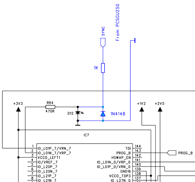
For safety reasons please add a reverse diode (e.g. 1N4148) over the LED D12.
This diode prevents negative voltage from going to the FPGA circuit IC7 from the sync input.
The LED D12 limits the positive voltage to proper level.
Here you can download the PCGU1000 circuit diagram and the board lay-out drawing:
box.com/shared/izxs8jm8rt
The FPGA circuit’s inputs are internally protected too.
For more info you can check this document:
xilinx.com/support/documenta … /ds099.pdf
Table 28: Absolute Maximum Ratings (Cont’d)