Hi,
i need a Function Generator with two channels with separated data.
It’s possible connect two PCGU1000 for synchronized output?
Thanks.
Hi,
i need a Function Generator with two channels with separated data.
It’s possible connect two PCGU1000 for synchronized output?
Thanks.
Hi,
From what I have read in other places on this board is that this can not be done very easily.
Also, it is not very easy to get two PCGU1000 generators to run in the same PC.
Please see: viewtopic.php?f=11&t=1243
Here is one alternative solution: viewtopic.php?f=11&t=1671
[quote=“suchigno”]Hi,
i need a Function Generator with two channels with separated data.
It’s possible connect two PCGU1000 for synchronized output?
Thanks.[/quote]
Can you expand upon your need a bit further?
In the first there is no “data” being output from a function generator, even the most arbitrary waveform generator available is only capable of creating repetitive bursts of what might be considered “data”. Also a better definition of “synchronised output” would be helpful–synchronised in what relationship?
Thanks a lot,
for “data” mean waveform… but i need two different waveform (ex. one sine and una square) that must to start in the same time and with the same Hz
And also if use the both in programming mode (like NET language ecc ecc) and send the command for start in the same moment, of course is not realy synchronized 
Change PID and VID for connect two generator to the same Pc i think is not a big problem…
It is possible to synchronize two PCGU1000 generators. For the synchronized generator you have to use the pcgu1000.bit and pcgu1001.bit files from this package: box.com/s/rbg0i5q82hjgeor8drkr
Extract and copy the files to the folder where the modified version of the PCSU1000GU.exe exists.
Please see this thread how to download and use the PCSU1000GU.exe with the modified PID: viewtopic.php?f=11&t=1243
Here are images how to connect the SYNC OUT of the first generator to the synchronized generator:
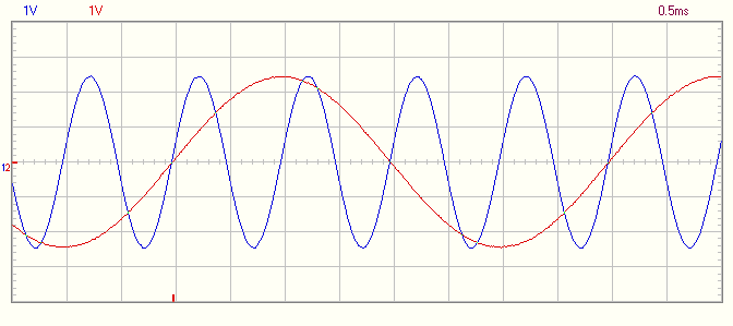
Here is an example how 250Hz signal of the first generator is synchronizing the other generator’s 1kHz signal: 
Good,
thanks a lot.
I try it.
S
The configuration software AN144SW on the Silabs site doesn’t work anymore.
Please use this older version: box.com/s/kmjvfn04pnd8vs6psufi
Thanks VEL255,
only one question:
the link from first generator to the second is by LED pin?
The idea is, put the different value in the both buffer (via usb), send start command to first generator and also the second start to generation?
[quote]the link from first generator to the second is by LED pin?[/quote]Yes.
It seems that this synchronization method is not according to your requirements anyhow.
This synchronization method is not usable if you need the both generators to start simultaneously.
This method is usable only for continuous wave.
The generators have to be started separately from two instances of the PcLab2000SE software.
ahh bad notice 
So, i think change hardware for my solution!!!
Thanks
S
[quote=“VEL255”]It is possible to synchronize two PCGU1000 generators. For the synchronized generator you have to use the pcgu1000.bit and pcgu1001.bit files from this package: box.com/s/rbg0i5q82hjgeor8drkr
Extract and copy the files to the folder where the modified version of the PCSU1000GU.exe exists.
[…]
[/quote]
Dear VEL255,
would it be possible to synchronise a PCGSU250 and a PCGU1000 for generating two impulse-waveforms with different frequencies?
I read this topic and I think it would be possible and there is no need to install the two different versions of PCSU1000GU.exe.
Thanks for your answer!
Bernd
Synchronizing the PCGU1000 by the PCSGU250 is very easy.
Just download the pcgu1000.bit and pcgu1001.bit files from this site:
box.com/s/rbg0i5q82hjgeor8drkr
Copy the two files to the PCLab2000SE installation folder.
Default:
C:\Program Files\Velleman\PCLab2000SE
In 64-bit operating systems:
C:\Program Files (x86)\Velleman\PCLab2000SE
Connect the PCSGU250 function generator output via a resistor (1k) to the “lower” leg of LED D12 in the PCGU1000 (the red alligator clip in the previous image). Connect the GND lead to the “upper” leg of the LED.
The signal amplitude from the PCSGU250 must be adequate for proper synchronization.
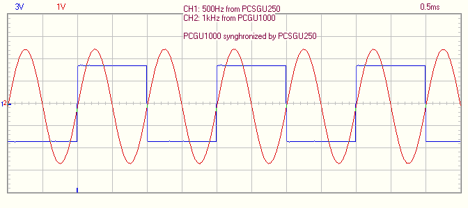
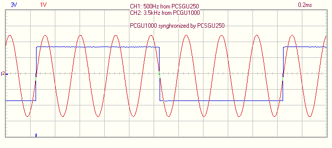
Here are examples how 1kHz and 3.5kHz sine wave from the PCGU1000 is synchronized by 500Hz square wave from the PCSGU250:


Dear VEL255,
thank you very much for your quick response and the answer!
I will buy a PCGU1000 the next days as an addition to the PCGSU250 and try a little.
When the combo will work together I will post it here.
Greetings,
Bernd
For safety reasons please add a reverse diode (e.g. 1N4148) over the LED D12.
This diode prevents negative voltage from going to the FPGA circuit IC7 from the sync input.
The LED D12 limits the positive voltage to proper level.
The FPGA circuit’s inputs are internally protected too.
For more info you can check this document:
xilinx.com/support/documenta … /ds099.pdf
Table 28: Absolute Maximum Ratings (Cont’d)