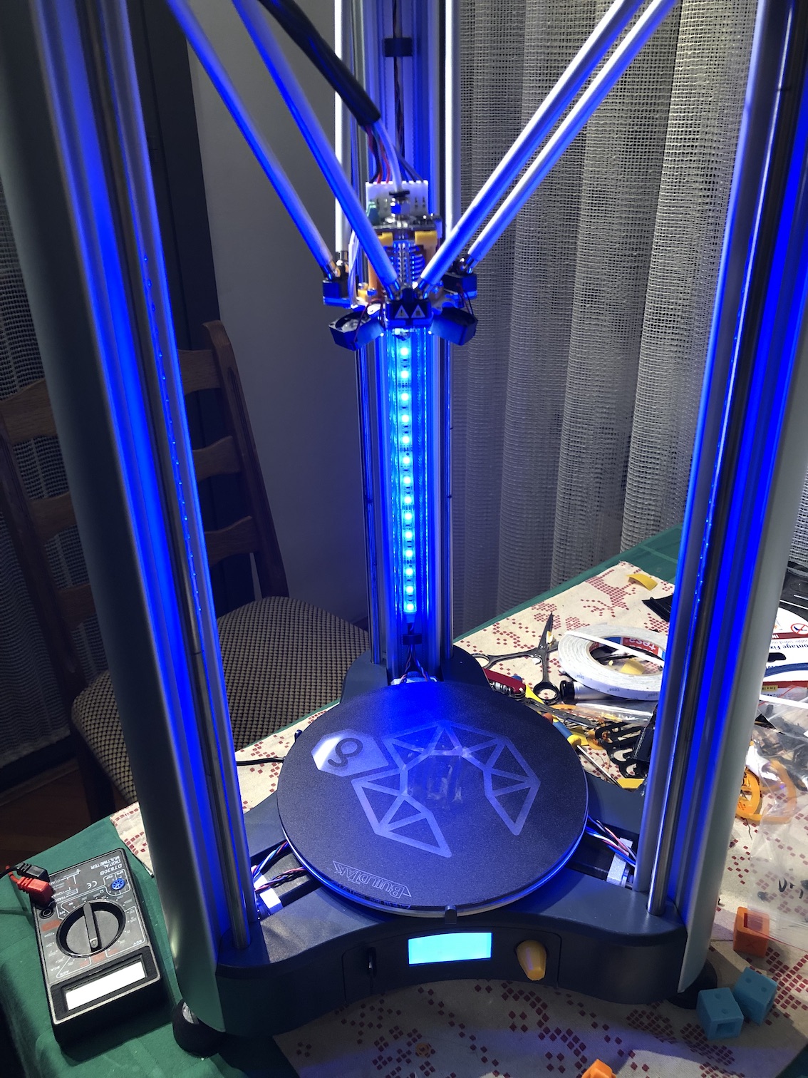
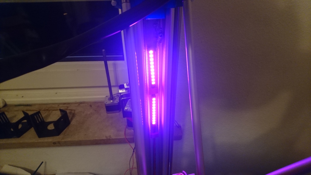
I thought it was kinda sad K8800 didn’t get a LED kit like the K8400, so i decided to give it some bling on my own 
Yes, it has PWM.
No, it’s not Neopixels.
I’ve desoldered the beeper and its resistor (couldn’t hear it unless my face was practically in the printer anyways), as well as the pin 13 LED and its resistor, and reused those pins for G and B. Then i’ve soldered an enamel wire to one of the unused PWM pins on the Atmega 2560, immobilised it with hotglue, and soldered the R to that.
R, G, B and GND from the board go to a little piece of scrap veroboard with NPN transistors and resistors, that serves as the driver for the strips. The power comes from the unused 15V header, and goes through a DC-DC buck converter i had (incidentally, Velleman’s), tuned to about 9-10V so the strips don’t glare too much.
By the way, whoever designed the board for the K8800 wasn’t quite thinking straight - almost all of the PWM pins on the Atmega are unused, those that are used were used for silly things that don’t need PWM at all, and the extra unused GPIO header is all non-PWM pins, except for pin 5, which is a PWM pin, but not when using Marlin, since its timer is used for other things (namely, the stepper ISR). So wasteful.
PS: Please excuse the mess, i ran out of space on my workbench and ended up doing the final reassembly on the kitchen table.
3 Likes
Very interesting mod!
Would you also share us your modifications to the Marlin firmware? Sorry, I’m not so deeply in that matter, but what is the problem with the PWM of pin 5?
No modifications needed, really.
You just need to uncomment this bit in the Configuration.h:
//#define RGB_LED
and configure the pins immediately below:
#if ENABLED(RGB_LED) || ENABLED(RGBW_LED)
  #define RGB_LED_R_PIN 34
  #define RGB_LED_G_PIN 43
  #define RGB_LED_B_PIN 35
  #define RGB_LED_W_PIN -1
#endif
The problem with the PWM on pin 5 is there is no PWM on pin 5 if you’re using Marlin. PWM on AVR microprocessors is ran via its hardware based timers. Atmega 2560 has 6 timers, but not all of them are available to all pins - they’re hardwired to specific timers.
The timer used to drive PWM on pin 5 happens to be the same timer that Marlin uses to time its stepper interrupt routine, so it cannot be repurposed for driving PWM. Pin 5 also happens to be literally the ONLY available PWM pin on the header Velleman/Vertex people pulled out to the (unused) expansion header on the PCB.
Of the remaining PWM enabled pins, only two have traces leading from the Atmega - the one that goes to the buzzer, and the one that goes to the CPU LED. The rest are left floating and unused.
Thank you for your explanation.
This Arduino pin numbering puzzles me all the time. I think PCB5 is pin 11 not 5. (??)
So you are using pin 6 aka beeper_PIN, aka PH3 for RGB_LED_G_PIN and pin 13 aka PB7 for RGB_LED_B_PIN ?
I’m wondering why in Configuration.h the comment says:
“If pins are PWM capable (e.g., 4, 5, 6, 11) then a range of luminance values can be set from 0 to 255.”
both 5 and 11 should work.
Pins 34, 43 and 35 are not even PWM
here is some pinout that I found:
https://camo.githubusercontent.com/23bfc6526ff789019be6888d094ca88f9603e4d5/68747470733a2f2f692e696d6775722e636f6d2f4f37577457416a2e6a7067
Sorry, yeah, meant pin 11, i.e. PB5.
You can’t use that one for PWM, its timer is tied up with the stepper ISR (OC1A).
If you don’t believe me, try it for yourself.
You can use PB7 (CPU LED) and PH3 (BEEPER). Everything else is either necessary for normal functioning of the printer, or not routed from the MCU.
That means you need to solder a wire to one pin yourself if you want RGB with PWM.
No worries, I do believe you. I’m just wondering that the Marlin Configuration.h comment recommends the use of pin 11 when it is known that it is not usable fort standard PWM. I think pin 12 and 13 are tied to the same timer 1 and should not work either.
here I ran a M43 (debug pins) on my K8800:
07:38:22.948 : PIN:   0   Port: E0        RXD                         protected
07:38:22.949 : PIN:   1   Port: E1        TXD                         protected
07:38:22.953 : PIN:   2   Port: E4        <unused/unknown>            Input  = 0    TIMER3B   PWM:     0    WGM: 1    COM3B: 0    CS: 3    TCCR3A: 1    TCCR3B: 3    TIMSK3: 0
07:38:22.954 : PIN:   3   Port: E5        X_MAX_PIN                   protected
07:38:22.959 : PIN:   4   Port: G5        <unused/unknown>            Input  = 0    TIMER0B   PWM:   128    WGM: 3    COM0B: 0    CS: 3    TCCR0A: 3    TCCR0B: 3    TIMSK0: 5   compare interrupt enabled   overflow interrupt enabled
07:38:22.962 : PIN:   5   Port: E3        <unused/unknown>            Input  = 0    TIMER3A   PWM:     0    WGM: 1    COM3A: 0    CS: 3    TCCR3A: 1    TCCR3B: 3    TIMSK3: 0
07:38:22.966 : PIN:   6   Port: H3        BEEPER_PIN                  Output = 0    TIMER4A   PWM:     0    WGM: 1    COM4A: 0    CS: 3    TCCR4A: 1    TCCR4B: 3    TIMSK4: 0
07:38:22.969 : PIN:   7   Port: H4        CASE_LIGHT_PIN              Output = 1    TIMER4B   PWM:     0    WGM: 1    COM4B: 0    CS: 3    TCCR4A: 1    TCCR4B: 3    TIMSK4: 0
07:38:22.971 : PIN:   8   Port: H5        FAN_PIN                     protected
07:38:22.972 : PIN:   9   Port: H6        CONTROLLER_FAN_PIN          protected
07:38:22.973 : .                          FAN1_PIN                    protected
07:38:22.975 : PIN:  10   Port: B4        HEATER_0_PIN                protected
07:38:22.980 : PIN:  11   Port: B5        <unused/unknown>            Input  = 0    TIMER1A   PWM:  2000    WGM: 4    COM1A: 0    CS: 2    TCCR1A: 0    TCCR1B: 10    TIMSK1: 2   non-standard PWM mode   compare interrupt enabled
07:38:22.984 : PIN:  12   Port: B6        <unused/unknown>            Input  = 0    TIMER1B   PWM:     0    WGM: 4    COM1B: 0    CS: 2    TCCR1A: 0    TCCR1B: 10    TIMSK1: 2   non-standard PWM mode
07:38:22.988 : PIN:  13   Port: B7        <unused/unknown>            Output = 1    TIMER0A   PWM:     0    WGM: 3    COM0A: 0    CS: 3    TCCR0A: 3    TCCR0B: 3    TIMSK0: 5   overflow interrupt enabled
07:38:22.991 : .                  TIMER1C is also tied to this pin                  TIMER1C   PWM:     0    WGM: 4    COM1C: 0    CS: 2    TCCR1A: 0    TCCR1B: 10    TIMSK1: 2   non-standard PWM mode
07:38:22.993 : PIN:  14   Port: J1        Y_MAX_PIN                   protected
07:38:22.995 : PIN:  15   Port: J0        <unused/unknown>            Input  = 0
07:38:22.996 : PIN:  16   Port: H1        BTN_EN2                     Input  = 1
07:38:22.998 : PIN:  17   Port: H0        BTN_EN1                     Input  = 1
07:38:22.999 : PIN:  18   Port: D3        <unused/unknown>            Input  = 0
07:38:23.001 : PIN:  19   Port: D2        <unused/unknown>            Input  = 0
07:38:23.002 : PIN:  20   Port: D1        KILL_PIN                    Input  = 1
07:38:23.003 : .                          SDA                         Input  = 1
07:38:23.005 : PIN:  21   Port: D0        SCL                         Input  = 0
07:38:23.006 : .                          SD_DETECT_PIN               Input  = 0
07:38:23.008 : PIN:  22   Port: A0        <unused/unknown>            Input  = 0
07:38:23.010 : PIN:  23   Port: A1        BTN_ENC                     Input  = 1
07:38:23.011 : PIN:  24   Port: A2        E0_ENABLE_PIN               protected
07:38:23.013 : PIN:  25   Port: A3        SDSS                        Output = 1
07:38:23.014 : PIN:  26   Port: A4        E0_STEP_PIN                 protected
07:38:23.015 : PIN:  27   Port: A5        DOGLCD_A0                   Output = 1
07:38:23.017 : .                          LCD_PINS_RS                 Output = 1
07:38:23.018 : PIN:  28   Port: A6        E0_DIR_PIN                  protected
07:38:23.020 : PIN:  29   Port: A7        DOGLCD_CS                   Output = 1
07:38:23.021 : .                          LCD_PINS_ENABLE             Output = 1
07:38:23.022 : PIN:  30   Port: C7        E1_ENABLE_PIN               Output = 1
07:38:23.025 : PIN:  31   Port: C6        LCD_PINS_D7                 Input  = 0
07:38:23.026 : PIN:  32   Port: C5        E1_STEP_PIN                 Output = 0
07:38:23.028 : PIN:  33   Port: C4        LCD_PINS_D6                 Input  = 0
07:38:23.029 : PIN:  34   Port: C3        E1_DIR_PIN                  Output = 0
07:38:23.031 : PIN:  35   Port: C2        LCD_PINS_D5                 Input  = 0
07:38:23.032 : PIN:  36   Port: C1        HEATER_BED_PIN              protected
07:38:23.033 : PIN:  37   Port: C0        LCD_PINS_D4                 Input  = 0
07:38:23.035 : PIN:  38   Port: D7        X_ENABLE_PIN                protected
07:38:23.036 : PIN:  39   Port: G2        <unused/unknown>            Input  = 0
07:38:23.039 : PIN:  40   Port: G1        <unused/unknown>            Input  = 0
07:38:23.040 : PIN:  41   Port: G0        <unused/unknown>            Input  = 0
07:38:23.041 : PIN:  42   Port: L7        <unused/unknown>            Input  = 0
07:38:23.043 : PIN:  43   Port: L6        <unused/unknown>            Input  = 0
07:38:23.046 : PIN:  44   Port: L5        <unused/unknown>            Input  = 0    TIMER5C   PWM:     0    WGM: 1    COM5C: 0    CS: 3    TCCR5A: 1    TCCR5B: 3    TIMSK5: 0
07:38:23.050 : PIN:  45   Port: L4        <unused/unknown>            Input  = 0    TIMER5B   PWM:     0    WGM: 1    COM5B: 0    CS: 3    TCCR5A: 1    TCCR5B: 3    TIMSK5: 0
07:38:23.051 : PIN:  46   Port: L3        Z_STEP_PIN                  protected
07:38:23.053 : PIN:  47   Port: L2        <unused/unknown>            Input  = 0
07:38:23.054 : PIN:  48   Port: L1        Z_DIR_PIN                   protected
07:38:23.056 : PIN:  49   Port: L0        <unused/unknown>            Input  = 0
07:38:23.058 : PIN:  50   Port: B3        AVR_MISO_PIN                Input  = 1
07:38:23.059 : .                          MISO_PIN                    Input  = 1
07:38:23.060 : PIN:  51   Port: B2        AVR_MOSI_PIN                Output = 1
07:38:23.062 : .                          MOSI_PIN                    Output = 1
07:38:23.075 : PIN:  52   Port: B1        AVR_SCK_PIN                 Output = 0
07:38:23.075 : .                          SCK_PIN                     Output = 0
07:38:23.075 : PIN:  53   Port: B0        AVR_SS_PIN                  Output = 1
07:38:23.075 : .                          LCD_SDSS                    Output = 1
07:38:23.075 : .                          SS_PIN                      Output = 1
07:38:23.075 : PIN:  54   Port: F0 (A 0)  X_STEP_PIN                  protected
07:38:23.075 : PIN:  55   Port: F1 (A 1)  X_DIR_PIN                   protected
07:38:23.076 : PIN:  56   Port: F2 (A 2)  Y_ENABLE_PIN                protected
07:38:23.076 : PIN:  57   Port: F3 (A 3)  <unused/unknown>   Analog in =   499   Input  = 0
07:38:23.077 : PIN:  58   Port: F4 (A 4)  <unused/unknown>   Analog in =   429   Input  = 0
07:38:23.079 : PIN:  59   Port: F5 (A 5)  <unused/unknown>   Analog in =   372   Input  = 0
07:38:23.081 : PIN:  60   Port: F6 (A 6)  Y_STEP_PIN                  protected
07:38:23.082 : PIN:  61   Port: F7 (A 7)  Y_DIR_PIN                   protected
07:38:23.084 : PIN:  62   Port: K0 (A 8)  TEMP_BED_PIN                protected
07:38:23.085 : PIN:  63   Port: K1 (A 9)  Z_ENABLE_PIN                protected
07:38:23.088 : PIN:  64   Port: K2 (A10)  <unused/unknown>   Analog in =   689   Input  = 1
07:38:23.090 : PIN:  65   Port: K3 (A11)  <unused/unknown>   Analog in =   578   Input  = 1
07:38:23.091 : PIN:  66   Port: K4 (A12)  Z_MAX_PIN                   protected
07:38:23.093 : PIN:  67   Port: K5 (A13)  TEMP_0_PIN                  protected
07:38:23.094 : PIN:  68   Port: K6 (A14)  Z_MIN_PIN                   protected
07:38:23.095 : PIN:  69   Port: K7 (A15)  FIL_RUNOUT_PIN              Input  = 1
I guess “non-standard PWM mode” means software PWM.
1 Like
So, we do not have enough PWM pins broken pout, I2C pins are also reused, but we do have SPI MOSI/MISO pins available (SK7).
So what do you think about this:
It is a SPI controlled 24 channel PWM driver so you can control 8 RGB-LEDs with it. There is just a little modification in Marlin required as I haven’t seen a TLC5947 support there yet.
Marlin already uses SPI to talk to some of the SPI-configured Trinamic drivers, so that should be fairly easy to implement. An easier (but more expensive) way out is to just use Neopixels (WS2812) since there’s already fully built in support for that, i believe.
Ah! Neopixels are Brightdots right? (please correct me if I’m wrong)
https://www.vellemanformakers.com/product/large-brightdot-pack-vmw104/
I think that are not that expensive and it looks like super easy to implement:
 // Support for Adafruit Neopixel LED driver
//#define NEOPIXEL_LED
#if ENABLED(NEOPIXEL_LED)
  #define NEOPIXEL_TYPE   NEO_GRBW // NEO_GRBW / NEO_GRB - four/three channel driver type (defined in Adafruit_NeoPixel.h)
  #define NEOPIXEL_PIN    4        // LED driving pin on motherboard 4 => D4 (EXP2-5 on Printrboard) / 30 => PC7 (EXP3-13 on Rumba)
  #define NEOPIXEL_PIXELS 30       // Number of LEDs in the strip
  #define NEOPIXEL_IS_SEQUENTIAL   // Sequential display for temperature change - LED by LED. Disable to change all LEDs at once.
  #define NEOPIXEL_BRIGHTNESS 127  // Initial brightness (0-255)
  //#define NEOPIXEL_STARTUP_TEST  // Cycle through colors at startup
#endif
1 Like
AFAIK, yeah, they’re one and the same. Everyone has their own name for it nowadays.
The chip (integrated into each LED) is WS28xx (usually WS2812).
Communication is fairly simple and bitbanged, so it doesn’t require any specific pins, as far as i know.
Hi,
I gave it a try with Velleman’s Large Brightdot module. I realized that the Marlin Neopixel support was not there in 1.1.4 and I did not want to change to a more recent version so I tried to back port the required stuff. You can find my changes to the firmware here:
Marlin 1.1.4 changed for Brightdot/Neopixel
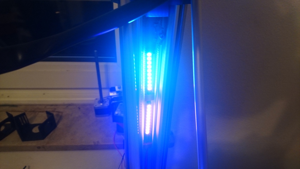
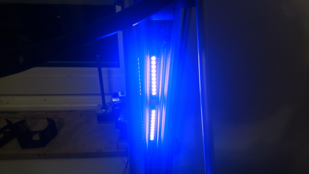
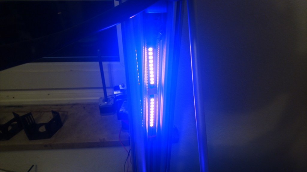
This is now when heating up the nozzle:
4 Likes
Awesome stuff!
There’s one more tweak i keep meaning to do but keep not finding the time to…
Original LED strip “event” support in Marlin was built for printers with heated beds, so the color status indication and progression is kinda wonky on the K8800. It should be fairly easy to change the range a bit.
1 Like
My modified K8800 has a heated bed.
I agree it can be done nicer. Instead going from blue to violet and then from violet to red it would be better to go from blue to red for both bed and nozzle. And in case for the Neopixels it would also work to dedicate have of the pixels to the bed and the other half to the nozzle.