Printer stops after 30 minutes

Hello people,

I have a Velleman K8200 since maybe a few months now (by school).
I enjoy the printer much, and it did a good job at first when it was in my friend’s house.
But since i have the printer all prints stop after about 30 min.

Here i have a picture of the repetier-host log while the error appears.

(While i’m not sure if this works here a link: http://i60.tinypic.com/2z818nk.png )

I have tested if i have enough Volt, and while printing I have about 15.3 V
But i was not measuring while the error appeared.

Does any have a solution? Or does anyone now the problem via the errors?

Much thanks in advance,
Mart 17

The log shows a brown out reset.

This is mostly caused by a overloaded or faulty 15v power supply.
I suggest to switch to a mor powerful 15v supply or power the heatbed from a second supply.

Did you try to run a print without the heatbed on?
If that runs fine the power supply is pobably good, but has too less power.
The stock supply is on the edge of it’s capabilities with heatbed on.

cheers,

Christian

Hey,

Thanks for ur reply,
Printing is now runing about 1.5 hours without heated bed, so seems to be good.
It’s running without filament though, i don’t think it would matter. (did it because now i have first layer problems because the bed was of, so it would have been filament waste)

I do not have a lot of experience with electronics, so if u could help with with powering the bed with a different power supply, that would be cool

greetings,
Mart

There are basically 2 ways to power the heatbed from a second source.

  1. use a Mosfet circuit to switch the 24V
    You can build one yourself (circuit diagram and build pictures here on the forum) or by an available “power expander”.

  2. use a simple relay to switch the 24V
    look here for a hookup guide : viewtopic.php?f=53&t=12955&p=71515&hilit=relay#p71515

Hello again,

I think i will need a bit more explanation. I’m litteraly a noob at this lol. I just want the must simple solution :wink:

First of all i have 2 old computer power supply’s, would any of them do?

  1. http://i61.tinypic.com/29f8aax.jpg
  2. http://i57.tinypic.com/2cz2ddk.jpg

I have searched for a Mosfet and i think i understand that, u can just buy them, right?
What i came up with is something like this:

The positive wire goes to the bed (don’t now if it should be the left on or the right one)
Negative wire goes out the bed, goes in to the drain and comes out the source again.
And then i quessed the far most right wires on the heated bed should go to the gate? (the single wires)

There is also something as a N-channel or P-channel, which one do i need?
I have a really old laptop is that usefull for parts?

Sorry for my stupidity
Greetings, Mart

[quote=“JustMart”]Hello again,
First of all i have 2 old computer power supply’s, would any of them do?

  1. http://i61.tinypic.com/29f8aax.jpg
  2. http://i57.tinypic.com/2cz2ddk.jpg
    [/quote]

I think both supplies will be too weak to power the heatbed properly.
Have a look at these :

reichelt.de/MW-GS120A24/3/in … anwell+24v
reichelt.de/index.html?&ACTION=446&LA=446
I use the first one by now, but i’m currently upgrading to the second, for a different headbed PCB with more power.

For the MOSFET:

P Channel

To turn a P channel MOSFET on, you apply a negative voltage to the gate. This voltage is negative relative to ground. In a circuit, you connect the P channel MOSFET’s source terminal to a positive voltage supply and the drain to a resistor connected to ground; the resistor limits the current flowing through the transistor. The circuit diagram symbol for a P channel MOSFET has an arrow pointing away from the gate.

N Channel

An N channel MOSFET turns on when you apply a positive voltage at its gate terminal. The voltage is greater than the positive voltage supply at the drain terminal. A resistor between the positive supply and the drain limits current; for an N channel MOSFET, the source terminal connects to ground. The circuit symbol for an N channel MOSFET has an arrow pointing toward the device’s gate.

So you would need an Logic-Level (5v signal) compatible N-Channel MOSFET
Also make sure the chosen type has an extremely low “on resistance” (RDSon) of 0.005 Ohms or less, to prevent heating it up too much.
For example : reichelt.de/index.html?&ACTION=446&LA=446

The on board MOSFET can’t take the current needed for the heated bed so you need to insert a dedicated circuit that can.

Two options :

  1. Buy a ready made one :&

  2. Build one yourself :

    Connectors and wires

             one 2 pins : [reichelt.de/PSK-254-2W/3/ind ... SEARCH=psk](http://www.reichelt.de/PSK-254-2W/3/index.html?&ACTION=3&LA=446&ARTICLE=14857&artnr=PSK+254%2F2W&SEARCH=psk)
             and one 4 pins : [reichelt.de/PSK-254-4W/3/ind ... SEARCH=psk](http://www.reichelt.de/PSK-254-4W/3/index.html?&ACTION=3&LA=446&ARTICLE=694&artnr=PSK+254%2F4W&SEARCH=psk)
             Molex connector to plug on the controller board.
             [img]http://cdn-reichelt.de/resize_70x70/web/artikel_ws/C151/PS25WEIS.jpg[/img]
             DON'T FORGET TO ORDER THE CONTACTS! : [reichelt.de/PSK-KONTAKTE/3/i ... SEARCH=psk](http://www.reichelt.de/PSK-KONTAKTE/3/index.html?&ACTION=3&LA=446&ARTICLE=14861&artnr=PSK-KONTAKTE&SEARCH=psk)
             [img]http://cdn-reichelt.de/resize_70x70/web/artikel_ws/C151/PSKKONT.jpg[/img]
             2 x 0.5 or 0.75 mm (speaker cable or 2 pole mains wire for instance) wires for the heated bed. Smaller wires for the +15/24V and the thermistor.
    

    Soldering iron and solder

Below you can find the schematics and implementation to build a power expander yourself :

Components list :

1x IRLU8743PbF MosFet
1x SFH610A-1 Optocoupler (to isolate the microcontroller from the power circuit)
1x 1N4148 Diode
1x 1.2K Resistor
1x 2.2K Resistor
1x 2.7K Resistor
2x 2-pole Terminal block
1x 4-pole Terminal block
1x Strip Grid PCB

Here is a link to the WIKI article :
The article is for the k8400 (vertex) but it’s basically the same for the K8200

k8xxx-3dprinters.crimed.be/w … ted_bed/de

And here is the relay solution :

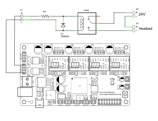
The diode (D1) protetcts the Mosfet on the Controller board from voltage spikes generated by the relay coil.

The resistor (R1) limits the current that flows to the relay coil, to prevent damage.
You need to calculate the needed value based on the rated current of your relay coil and the 15V output of the Heatbed output.
For example if your relay coil draws 30mA : R=U/I 15V/0.03A=500Ohm

Make sure The relay can take the current drawn by the Heatbed. (about 4.5A at 24V for the stock k8200 Heatbed)

cheers,

Christian

I just wanted to let you know how things are going.

I ordered all the parts, and after a bit a research I started assembeling everything.
I have just finished wiring everything up, and it works all fine first try :D.
Bed gets too a 100 degrees in about 10-15 minutes while heating the extruder so everything works fine (no brown out reset)

Thanks for all, i’ll be defenitelly hanging out here more often.

Greetings,
Mart

Nice to hear!

Happy printing!

Slicing is definitely completing 3d printer, I can also manually restart the print from where it stopped by editing the g-code and telling the print to start from the failure point. But this is getting tedious and it seems like the longer I get into a print the more it pauses.

I tried printing from an SD card and I get the same behaviour.3d printing mumbai pune maharashtra india

Thinking that there must be a power fault on the controller board or power supply that is causing it to abort the print.

Nothing shows up in the log though when I am printing from repetier.