The function generator shows severe amplitude degradation at higher frequencies. Or may be it is the scope, I connected the function generator directly to the scope input, I don’t have another scope. I starts around 50KHz. At 100KHz to 500KHz all signals have an amplitude an order of magnitude lower than what they should be. Square signals are rounded and very low in amplitude and sine waves have very low amplitude. It is as if there was a capacitor in parallel with the output. The program help talks about “activating the low pass filter in the function generator”, but it is not clear how it is activated or deactivated.
Is there a low pass filter ? How is it deactivated ?
The issue is related to a really crappy rise time on the generator output. About 2 usec. This causes the generator output to have a 3 db point of about 330khz, no where near the specified 0.2 usec. velleman.eu/distributor/prod … ?id=377622
◦square wave rise/fall time: 0.2µs
I suspect that the board was populated with an incorrect D/A deglitch filter capacitor or a substitution of the OP amp with one with a poorer slew rate.
What is the id and location of this cap so that we can change it out for the correct value since it is a PITA to do an out of country warranty exchange? People who have this scope are probably capable of making the change even if it is a SMT board. (not dense at all)
I pulled C72 (near pin 4 on IC12 LM6172). Measured as around 100 pF which seems a bit high for its function.
Unfortunately unit oscillates if not in place.
Pulled C117 with no effect (but it is part of the output feedback loop). Measured at around 10pF so I put it on C72 pads. This gets rise time down to about 400 nsec. It’s value is cleary still a bit too large, but I don’t have a meter that can read that low to know what the ‘correct’ value should be.
Having the schematic for the output stage would sure help troubleshoot this ‘build error’. Hint hint.
How did this fault get past quality control? Does Velleman not test the generator over the full output range?
The op amp they use is good for the task, 3000v/sec slew, 50mA output, 120 Mhz GBW.
It’s just built with some wrong parts that cause the bandwidth to be incorrectly limited.
It is very easy to pull these parts if you just use TWO soldering irons, one on each side to lift part off board.
Use solder wick to clean off residual solder and tweezer to control the placement.
I do have one request. Can you have the driver program FORCE a reload of the FPGA code when one goes from ‘demo’ to ‘active’ mode? It was a real PITA to have to rerun the program ever time I had reconnect the box after mucking with the parts.
[quote]Having the schematic for the output stage would sure help troubleshoot this ‘build error’.[/quote]Here is the link to download the generator schematic diagram and the PCB lay-out: box.net/shared/kp8lv17ot5
Schematic says C72 is supposed to be 22pF. The one that the unit had installed was 120 pF.
With the correct value installed, unit meets spec. 0.2 usec rise time with about a 8 % overshoot.
Be sure to use an NPO cap for stability with temperature changes.
C72 is just to the right and slightly above pin 4 of IC12 near the center of the board.
The generator amplitude is set with a 3 bit 5% resistor D/A for the main D/A reference input, and a R/2R resistor network which gets tapped by a 4051 mux. No wonder the amplitude calibration is all over the place.
Any chance we can get the software/firmware to support going out to 1 mHz or more?
The op-amp is rated to 120 Mhz, and the rest of the chain seems to be able to handle it. The only downside is that the distortion spec will be degrade above 500 kHz. I can live with that to get the extra range.
Thank you Velleman for the tech support. Unbelievably good.
[quote]Schematic says C72 is supposed to be 22pF. The one that the unit had installed was 120 pF.
With the correct value installed, unit meets spec. 0.2 usec rise time with about a 8 % overshoot.[/quote]It’s good to see you got the generator working without sending it to repair!
[quote]Any chance we can get the software/firmware to support going out to 1 mHz or more?
The op-amp is rated to 120 Mhz, and the rest of the chain seems to be able to handle it. The only downside is that the distortion spec will be degrade above 500 kHz. I can live with that to get the extra range.[/quote] Indeed, the op amp is capable beyond 1MHz but not the DAC.
See: cache.national.com/ds/DA/DAC0800.pdf
“The DAC0800 series are monolithic 8-bit high-speed
current-output digital-to-analog converters (DAC) featuring
typical settling times of 100 ns.”
That means you can update the DAC at 10 MHz, which gives 10 sample points for a 1 Mhz sine wave.
The settling time spec is also for ‘full scale’ change, so it will settle faster for the smaller steps between points on a sine or triangle wave. This also means it can generate a 5 Mhz square wave, but with subsequent filtering, it will actually be a sineish wave. I can live with that for the extra testing range it gives.
And your data sheet for the unit says that the generator DAC is updated at 12.5 Mhz so there is not reason to NOT provide a higher output frequency, as long as the spec says 'distortion specification will degrade above 500 KhZ).
You are right - we are using this DAC on very “safe area”.
Indeed, it is capable to produce somewhat higher frequency too but there may be some criticism concerning the wave form purity…
[quote]This also means it can generate a 5 Mhz square wave, but with subsequent filtering, it will actually be a sineish wave. I can live with that for the extra testing range it gives.[/quote]Here is the link where you can download a modified PCSGU250 program: box.net/shared/tnxc4aigss
You can select the frequency up to 5MHz.
Select the 1MHz (sine) 500KHz (square, triangle) frequency range.
Click the frequency window and enter the frequency.
Click “enter” button to confirm.
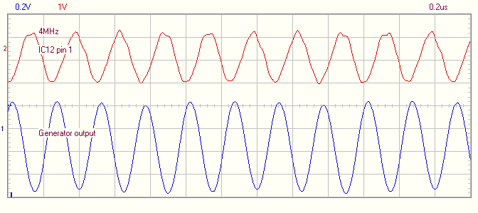
Thanks for the quick patch to the program to get the extra range.
3 db down at 2 Mhz is decent. Nothing at 5 Mhz because of the DAC noise/deglitch filter.
I’ll have to compute some new cap values for the low pass filter and check that the 4051 passes the signal without too much loss, but it should be possible to get an attenuated 5Mhz out of it since the chosen op amp has good GBW.
Imagine all the features that users could add if you went open source…
Thanks again for being so responsive to your users.
I am grateful to all the participants.
It helped me to solve the problem of bad pulses at the output of the generator.
In my opinion it was not a very good solution to apply to the regulator of the amplitude 74HCT4051.