I’ll power the necessary servo from a simple voltage regulator circuit connected directly to the power supply input. Regarding the signal to the servo, I just plan on using any of the loads of unused pins on the ATmega2560.
only 50 of the 100 pins are in use, and I should basically just be able to pick any one at random of the unused ones.
That leads to my question: does anyone with or without access to the PCB schematics know of any unused pins being connected to any test point or the like that would be easily accessed and soldered to. I would very much like not having to solder directly to the MCU’s legs (I always end up breaking stuff that way … >.<). I will disassemble my child and cat proofing printer cabinet and check the board myself tonight when the kids are asleep, but it would be awesome if someone on forehand knew of a good place to start.
for connecting the servo, you’ll probably need PWM capability.
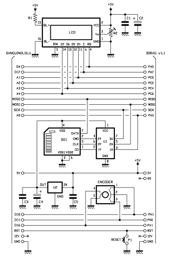
There are pins routed to the top right corner area that’s prepared for the extension connector, however, these pins (they’re noted in the schematic, PH0, PH1, PA1 and so on) are all just DIO. There are unused PWM pins (PH3, PH4 etc.) available, but they can only be accessed directly at the ATmega.
As I have understood it, Marlin uses the Arduino servo library, which doesn’t use PWM, so any pin should be usable.
So I am still looking for any unused pin wired away from the MCU to somewhere other than the extension connector (since I’ll be installing a wm8201 soon).
Yep, I see that in pins.h; but as i interpret it, that leaves chip pin 19 (arduino numbering 53), marked as SS in the main chart, unused, but still wired to the header. I assume that the vm8201 sold by Velleman adheres to the circuit chart on the 3drag home page I linked to, because on that the SS-pin from the connector when using the 3drag main board connects to X, which in my book means no connection, thus making it possible to use it for servo control, even with the vm8201 connected.
you may be right about D53, but I can’t confirm your assumption since I don’t know the VM8201 circuit. You’ll have to find it out on your own (or ask the VEL guys on Monday).
you may be right about D53, but I can’t confirm your assumption since I don’t know the VM8201 circuit. You’ll have to find it out on your own (or ask the VEL guys on Monday).
Cheers,
kuraasu[/quote]
Yup, I’ll have to wait for a definite answer 'til then I suppose.
What I plan to do now though is just soldering pins to the header in preparation for the VM8201, and use the pins with a female connector cable for now, and and then try out with the stand alone module when I receive my unit on tuesday.
Got it up and running with P53 yesterday night (at 3 am …). I almost ended up breaking the servo lever and smashed the hot end into the print bed a few times before getting a grip of the settings, but now it works like a charm.
I’ll report back when I receive my VM8201 on tuesday when I’ll see if the pins interfere; if not, I’ll make a simple passthrough board for the connector jacking into both P53, 5V and GND for the servo, and 15V through a voltage regulator circuit for 12V to a case fan. (I’ll probably make it anyway for easy access to the 5V, 12V and GND pins.)
Please tell us if the pins interfered - it would be great if not.
I have the VM8201 connected and been told in this forum that no pins where free from the connector.
I have also got my servo for auto-leveling working but I have soldered directly from MCU pin and do not
like it, it’s not the optimal solution for this environment.
Secondly, to get the servo working I had to start from latest Marlin from GitHub and tried to catch all settings
in “Velleman V2” and ported to latest Marlin. Everything is working fine but I have a strange sound from Y-stepper, (this
strange sound disappears if I revert firmware to “Velleman V2”. I have changed the files Config.h, Config_adv.h and pins.h
to what diff. in “Velleman V2” and can’t find what else to change - Any ideas, appreciate all help?
I’ll check tonight if the kids allow for it (by sleeping).
Regarding firmware, I just forked the latest Marlin and merged the settings from V2 from Velleman. You can find my working version on my github. (You of course need to change the probe coordinates and so on.) No wonky clicking for me. (I also enabled max oscillation of 15 Hz in firmware and lowered accelleration to 2000 m/s^2 to prevent skipping steps on narrow infills; so caveat emptor.)
you lowered the DEFAULT_MAX_ACCELERATION for X and Y to 2000 mm/s², true, but you increased DEFAULT_ACCELERATION at the same time. The latter value is the one that’s used for printing (unless a M204 command is sent), and the value in both V1 and “V2” firmware is 1000 mm/s².
Thanks for sharing your files, however this did not help either, went worse - same sound and small movements takes a lot of time while printing. Reverted back to my setup, with the weird sound.
Noticed that you can get rid of the servo jerking while not in use by defining following row, (it’s commented out by default) : #define PROBE_SERVO_DEACTIVATION_DELAY 300
I can now confirm that using pin 53 (MCU pin 19) labeled SS on the K8200 main board is working in conjunction with VM8201. At first I only got everything but the encoder wheel working, but that turned out being due to a cold solder joint, easily fixed.
Due to time constraints, I ended up doing the ugliest of hacks to get this tested:
I basically just soldered a new set of pins on the back side of the main board, to which I currently have connected 5V, GND and signal for the auto leveling servo. When I get time, I’ll probably make something more proper, like a pass through board for the cable connector with a standard servo connector.
Hi Velleman support
It would be appreciated with a statement regarding free pins on 18pin connector when VM8201 attached.
Previous statement from support team was that there is NO free pins when VM8201 is attached [url]Wiring of the VM8201]. The SS pin seems to be free (D53) according to tests made by magu.