I just received it, thought there would be at least a schematic and a user manual (who are not available as downloads), but … no ! Just nothing except assembly instructions.
Furthermore, I suspect the kit will not be able to generate the promised 30 V to test the forward voltage of higher voltage LED’s, because I don’t see any component that could be involved into a step-up converter…
I guess I will have to assemble it to find it out… or to be disappointed again !
Could you at least publish the schematics on the website, as for the other kits ?
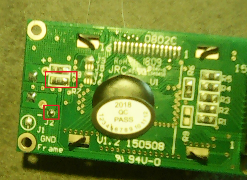
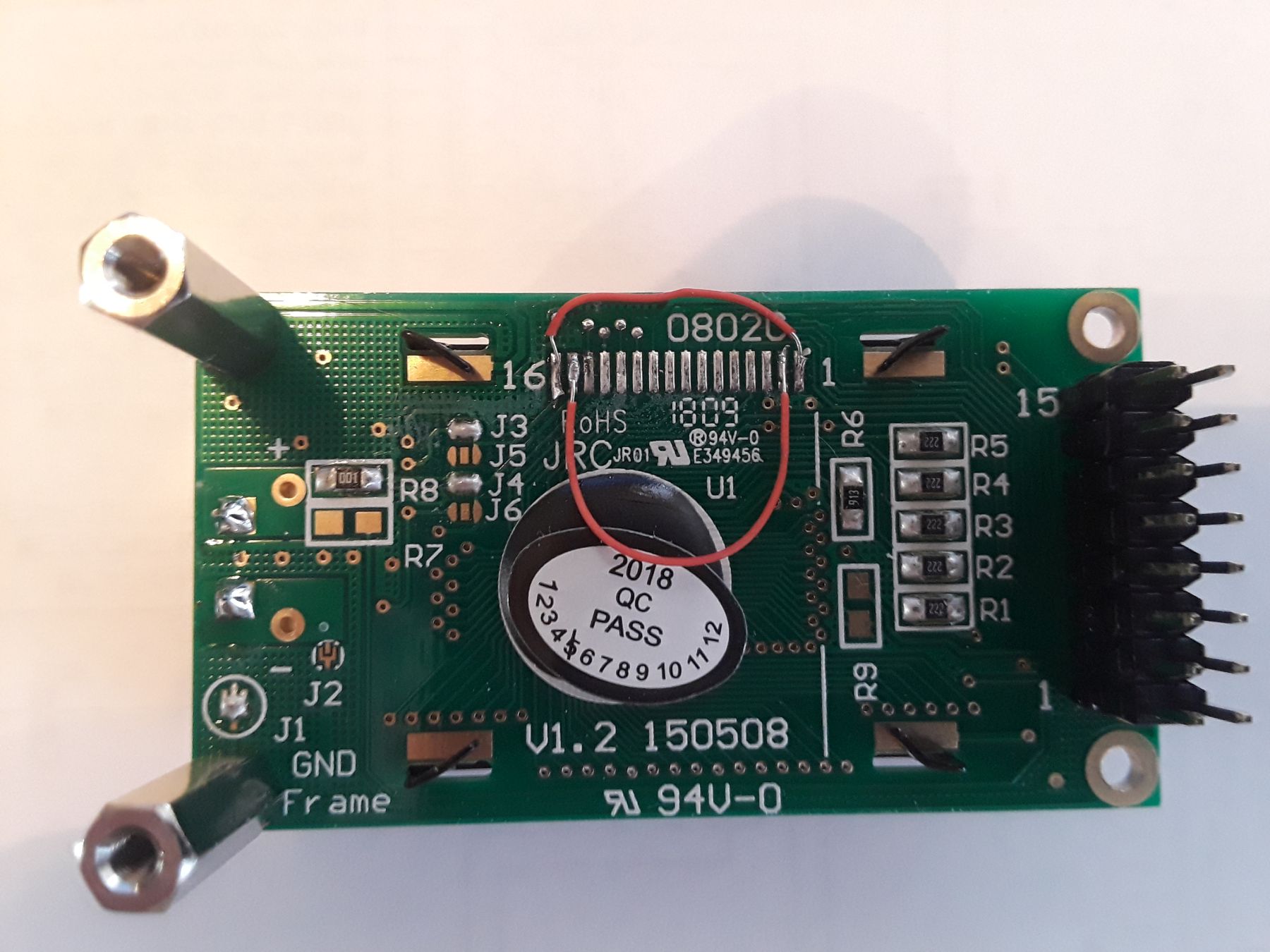
As to the backlight, its really simple. Make a connection between the “K” terminal and the GND pin (Pin 1) and also between the “A” terminal and the VDD pin (Pin 2). See the photo attached… the red wire on the LCD board is used to make these connections. The solder “stripes” are numbered 1 through 16 and correspond to the pins in the LCD board header. The wire used is 30-gauge wire-wrap wire. Any fine wire will work. You may want to adhere the wires to the board with some hot glue when finished with the connections.
It’s all set to go. Connect it as explained and shown in the photos and you’ll be rewarded with a nice pale red backlight. No need to add anything else….
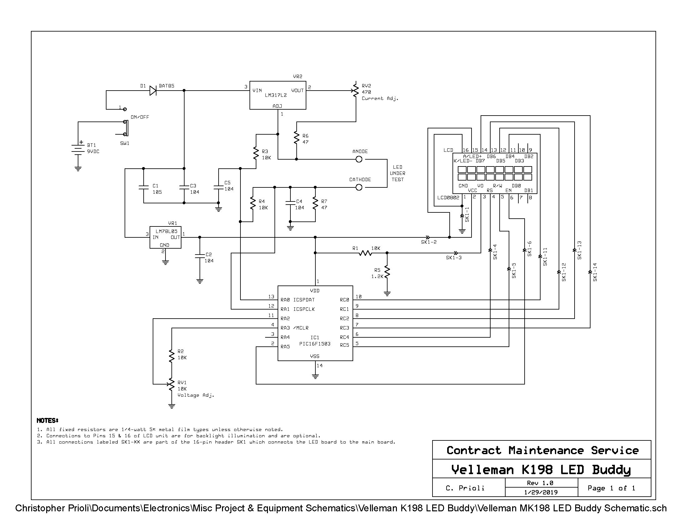
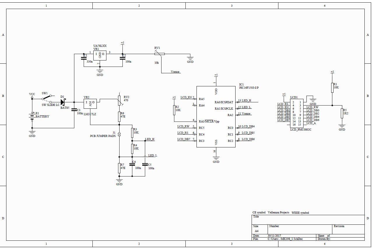
Thanks VEL337. I suggest that this schematics be published in the download section of the product page. So that people understand the real funciton and limitations of the LED Buddy.
For the backlight, considering there’s only one LED, and to not stress the 78L05 too much, I’ll put a resistance of 220 ohm. The current in the LED should be about 10 - 12 mA (Interesting trick : use the LED Buddy to measure and suggest the resistance by measuring its own backlight LED )
About the schematics, what is the purpose of JP1 ?
haha nice one!
JP1 is the contacts where you place the LED
And i will pass it along about the schematic on the download section
Have a nice weekend
VEL337
Interesting… My backlight is running 0.0093 A (9.3 mA) to give me the pale red color. A 180-ohm limiting resistor puts the backlight out completely. I think that I will experiment some more…
Chris is right: The backlight is orange/red (nice and warm color).
As I explained earlier, i used the LED buddy to measure the LEDs of its backlight by connecting the probes directly to the pins of the backlight LED’s.
I got a VF varying between 4.0 and 4.2 V. Probably 2 LED’s in series. The LED Buddy suggested me a 100 ohm resistor (closest value) to get a VF of approx 10 mA.
So, I soldered the resistor on the pads for R7, and also put a solder blob on the J2 jumper.
Ok you’re right
My memory let me down.
Still it’s a good practice to put a serie resistor before the leds
Also the schematic should be now available for download.

 )
)