I just assembled the radio but can´t get it running. Everything has been already checked: position, solder joints, voltage on each part.
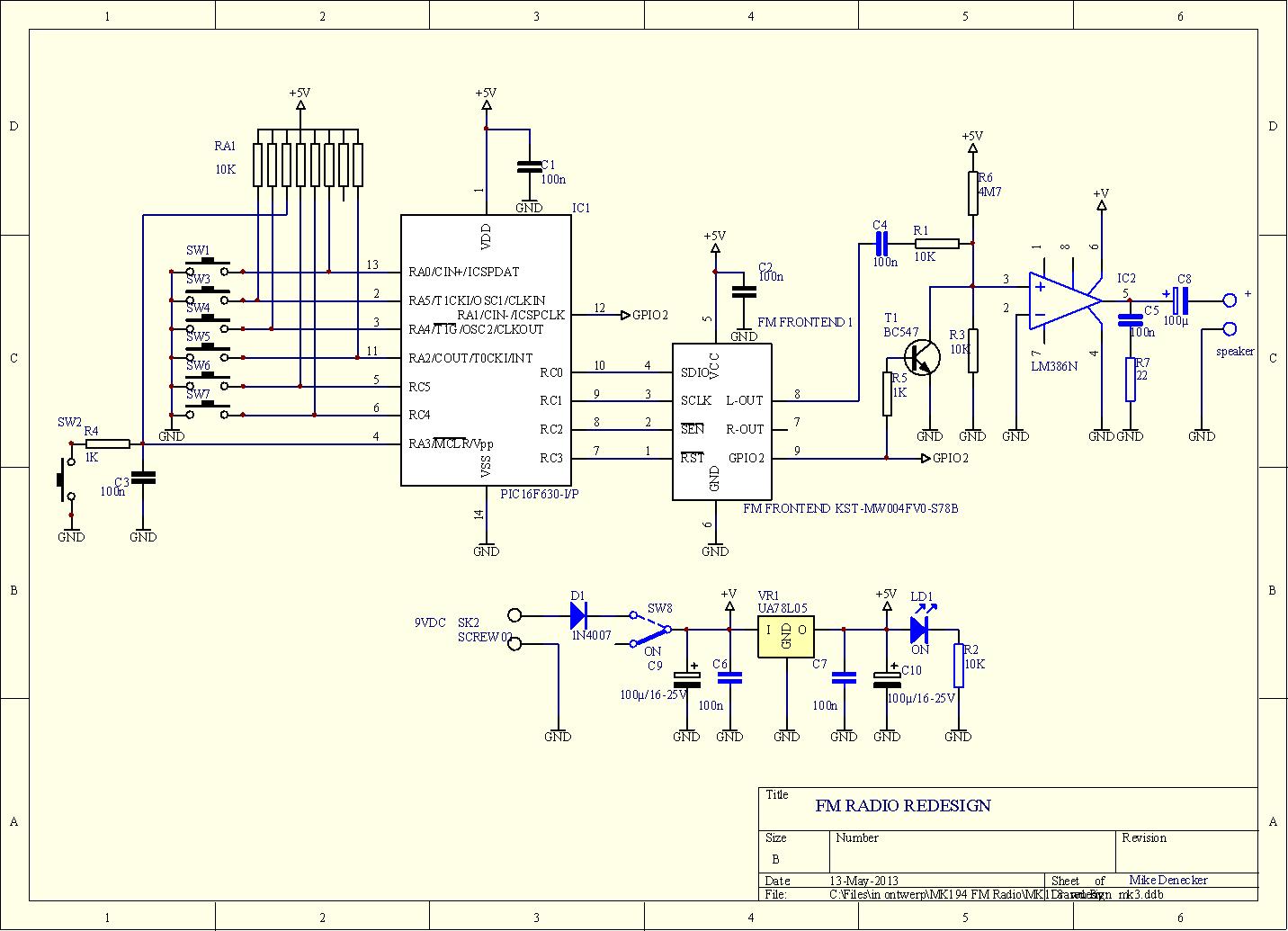
It is extremely difficult to isolate the mistake without a circuit diagram…
It would be nice if you could provide this anyhow.
Thank you very much in advance and have a nice day,
I have just built this radio and thanks for pointing me in the direction of the circuit diagram. My question is although the radio seems to work, the operation of the digital switches confuses me.
Top one searches for stations fine
2nd one is supposted to increase volume, mine changes frequency similar to top one
switches 3, 4, 5 6, 7 seem to work as indicated.
Any ideas where to look for solution
Regards
Chris G0EYO (radio ham)
Thanks Velleman
Can you tell me which switch on the circuit diagram relates to which function:
Search
Vol up
Vol down
Preset 1
Preset 2
Preset 3
Preset 4
This would help me where to look on the pcb
Thanks
Chris G0EYO
Sorted I had RA1 the wrong way round. Had not appreciated it had dot on end (should have read the instructions more carefully).
Thanks for the support. It is very good
Regards
Chris G0EYO
Hello every one .I am just constructing the mk194 digital radio on a bread board instead of the circuit pcb you get with the kit.I have had a look at the circuit diagram.thanks uploader for the circuit diagram couldn’t get it anywhere not even .maplin didn’t even have it.any way to my point on the circuit diagram there’s an arrow pointing to GPIO2 does any one know what this is .thanks for any help anyone can provide.
Sorry, circuit descriptions are not available.
Basically, the PIC just sends serial data to the FM front-end.
Complete protocol can be found in the front-end manual. http://www.velleman.eu/images/tmp/AN332.pdf
Please allow 1h for server refresh.
