Hey, guys.
I’ve just completed my MK144 and followed the instructions to the letter, but it doesn’t flash. When it has a battery connected, all six LEDs just remain on.
Is there a trick to make it flash, or have I messed something in the assembly?
The kit:
https://www.vellemanusa.com/products/view/?id=351408
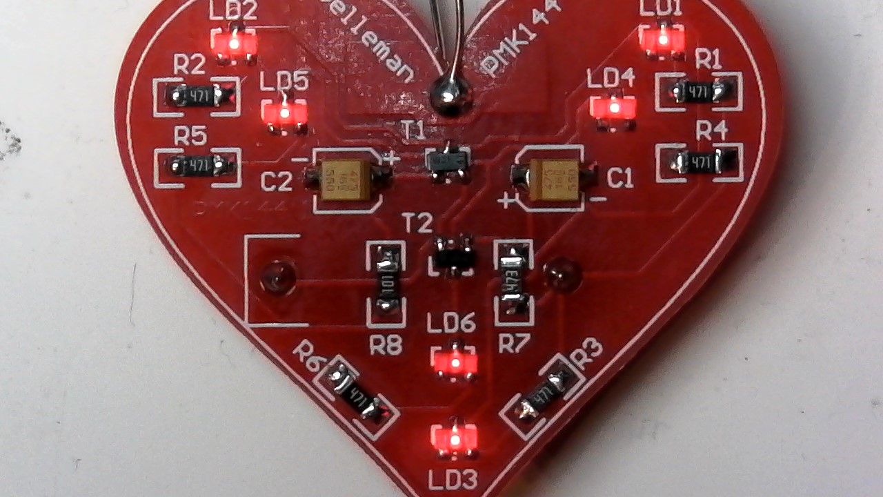
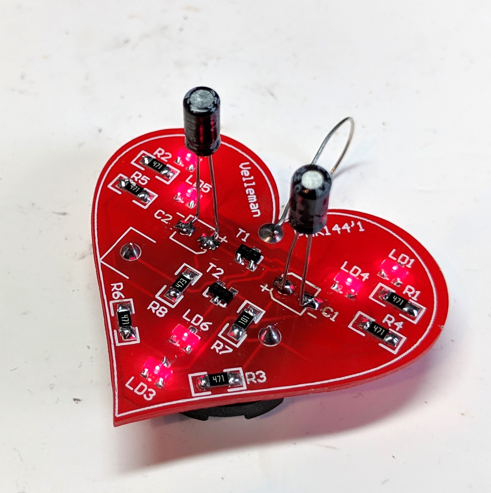
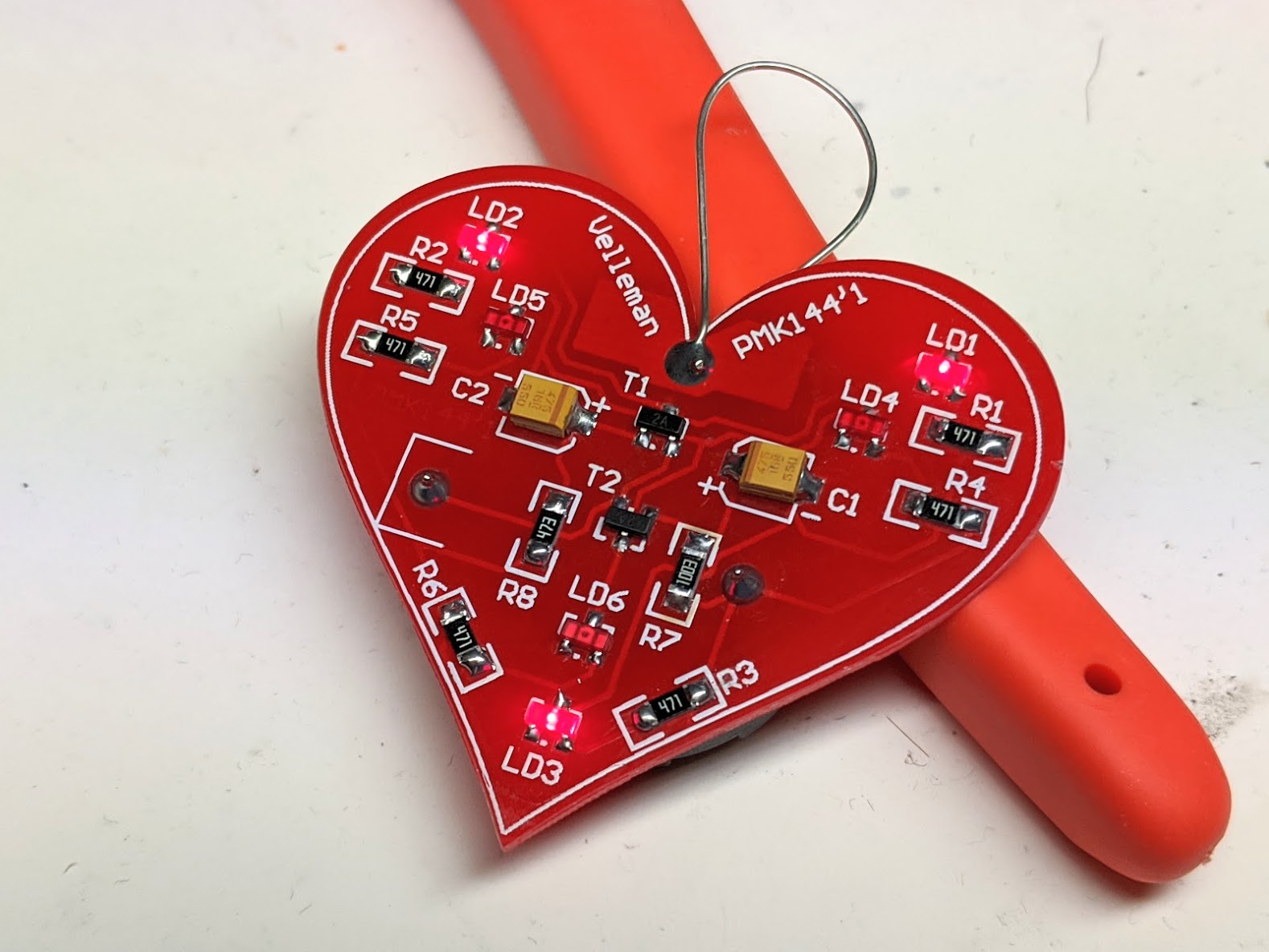
My completed heart:
Thanks,
Craig
It looks like you mounted R8 in R7 and R7 in R8
Whoops! It seems my ‘to the letter’ following of the instructions wasn’t entirely accurate! 
I’ve corrected that error, but it hasn’t changed anything - the LEDs still remain lit, with no flashing.
You might try heating the solder joint again until the solder flows
One of the legs on T2 looks like it may not have a good connection.
That’s just a shadow on the photograph, I think. I’ve double checked all of the solder joints to be sure, both physically and with my multi-meter and everything seems to be where it should be.
This would still be something to try.
It’s worked for others
Worth a shot! Will touch up all of the joints when I get a chance.
Just finished touching up all of the joints, re-flowed everything to be sure, but the LEDs still just stay lit, with no flashing. I’m wondering if some of my components are damaged, but I’m not sure how to check a transistor using a multi-meter.
Edit: I looked up transistors (I’ve never worked with them before!) and get the measurements of 0.09v between the Base and Emitter and 0.55v between the Base and Collector on T1, and 0.01v & 0.77v on T2. My interpretation of a bipolar junction transistor suggests that they’re both working correctly, so I’m a bit stumped as to the problem!
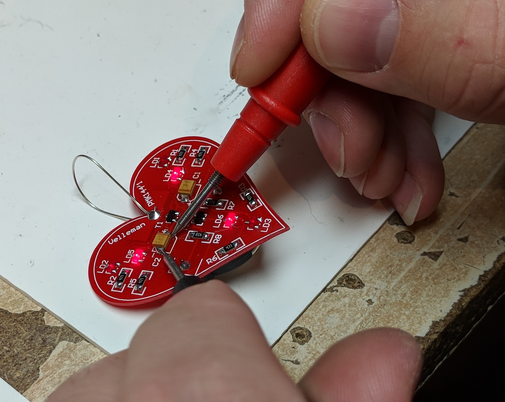
Interesting to note that when I take a measurement of the left capacitor (in capacitance mode), LD1, LD2 and LD3 start to flash, but only when my probes are in position. The right capacitor gives no measurement, so I removed it from the circuit… and it measures correctly.
I’ve replaced the right capacitor with a barrel capacitor and when taking a reading of the known-good capacitor. While installed on the board, I get no measurement.
If touching the left cap with the probes causes the circuit to flash, then it is probably the left capacitor that is not working properly. The probes have some internal capacitance of their own, and are augmenting the left cap when you touch it.
So I would focus my troubleshooting efforts there.
I thought that might be the case as well, so I removed both capacitors from the board and they’re showing the correct values on my meter. I tried swapping them over as well as just using one or the other, but no joy.
Tried a pair of electrolytic capacitors in place of the SMD capacitors and there is no change whatsoever to the LEDs, they’re staying on quite happily without any blinking whatsoever.
Greetings,
I was gifted this kit and experienced the same issue.
I have noticed both your kit and mine have the wrong vale of resistor for R7. The instructions want R7 to be 100K ohm, but our kits provides a 100 ohm.
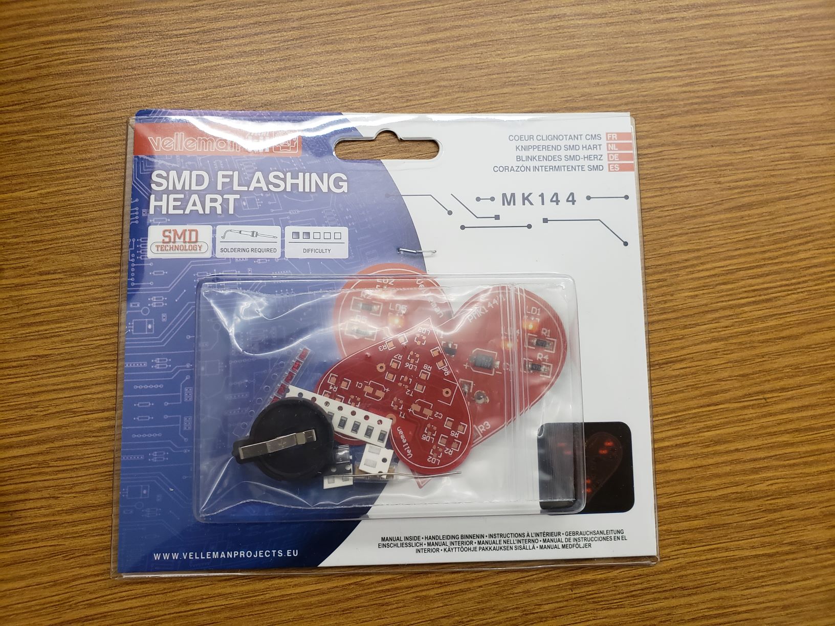
However the real issue is the two transistors they are marked as W2F41 measuring at 50V NPN. The schematic shows we need a 40V PNP transistor. Attached are an image of the kit in its package, my breadboard build, a video of the surface mount build with no flashing. And a video of my flashing breadboard build.
Poor poor quality control Vellman.
Wow, thank you for taking the time to do such a detailed analysis of the kit! I honestly didn’t even think to check the values of the supplied components, I just figured I must’ve messed something up!
Since Velleman haven’t bothered responding in order to send out the free replacement kits/components, I think I’ll just initiate a chargeback as the item being sold falls squarely under the ‘not fit for purpose’ portion of the Consumer Rights Act.
I won’t be buying anyone Velleman kits again.
All thanks to you, pinkbush! Thanks again. 
Nicely done, how exciting!
Good looking joints.