Hello, I have just finished my Quiztable MK133. It’s the first time I’m doing anything like this, so I’m an absolute beginner. I believe I followed the instructions quite neatly, but of course it does not work and I dont know where to start searching for errors.
When I push the Reset Button, two of the contestants led light up and only for when I keep it pushed. Nothing else reacts when I try pushing Buttons.
I edited the circuit diagram to show which of the led works. The green ones light up when I push the blue button as long as I keep pushing it. The red ones dont light up at all and all other buttons dont seem to work either.
Here are Pictures of the MK aswell. Its my first time soldering at all, so its quite poor.
Maybe someone sees where the soldering is that bad, it has to be done again. Or which of the components could be responsible….
English is not my native language, but I couldnt find any Help in german language. So I hope anybody understands what I’m trying to say, has mercy with my poor soul and will help me
Do you have a multimeter to do some continuity check ? (it is a way to control some soldering , like to do some measure control voltage and/or resistor value … and also to check if the LED are good …)
Are you sure there is no component polarity inversion ?
Are you sure there is no component permutation ? (like mixing between some resistors or between transistors )
You should also add a photo of the other PCB side … someone could see something …
A freshly new 9V battery is always better !
At first look at your photo, hard to tell if your soldering are good or not, photo quality / blurriness and the not shorten/cut-of components legs are confusing … ( like is the reset push bt is soldered or not ? )
And not having the PCB component layout don’t help to identify the soldering / components !
As it is not in the documentation https://www.velleman.eu/downloads/0/minikits/manuals/manual_mk133.pdf
maybe some Velleman support menber could help to find it … or an emply PCB ?
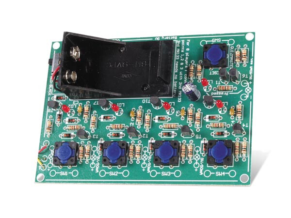
The product picture can help but not enough
Thank you both very much for your helpful comments. Its like VEL255 said…I didnt even notice there were two types of transistors.
So much for “I followed the instructions”