Hello velleman,
Ik have recently finished my LCD osilloscope. It worked for around 5 minutes and the stopped working. Now only the display back light tuns on but there is no data at all.
What can i do to fix this?
Hello velleman,
Ik have recently finished my LCD osilloscope. It worked for around 5 minutes and the stopped working. Now only the display back light tuns on but there is no data at all.
What can i do to fix this?
Please check the DC voltage on the test pin.
There should be about 1.65V.
This indicates the microcontroller IC3 is working.
Then check the voltages on connector SK1 on the top board.
(It is connected to the pin header SK7 on the bottom board.)
You can use the input ground lead as GND reference.
The voltages on the pins should be:
Top row from left to right 3.3, 0, 0, 0, 0, 0, 3.3, 0, 0.4
Bottom row 0, 3.3, 0, 0, 0, 0, 0, 3.3, 0
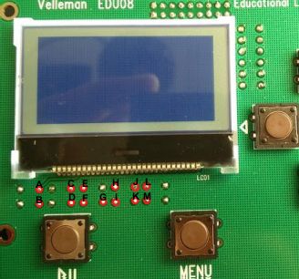
You can also check the voltages on the points marked A-M in this picture:
The voltages should be about:
A=9.2V
B=8.2V
C=7.2V
D=2.0V
E=1.0V
F=1.6V
G=7.2V
H=1.6V
I=4.6V
J=9.8V
K=1.6V
L=3.3V
M=11.2V
Ik measured all of Them and i got this:
Test pin: 1,66 V
Top row left tot right:
3,34. 3,33. 3,33. 3,33. 3,33. 0,0. 3,32. 0,0. 0,53
Bottom row left tot right:
0,0. 3,33. 3,33. 3,33. 3,33. 0,0. 3,3. 3,3. 0,0.
A 0,0
B 0,03
C 0,0
D 0,01
E 0,05
F 3,33
G 2,94
H 0,0
I 3,33
J 2,95
K 0,0
L 3,33
M 2,78
They are almost all wrong
These results may indicate the IC3 is not working OK.
Please check it is properly placed in the socket and check all the soldering.
Check also the display pins for possible solder bridges.
My display soldering is indeed a bit bad so i will try to redo all of them. I could not find something wrong with 1c3
I checked all of the display pins but found no shorts
Ok. Also possible disconnected (bad) solder joint may cause the problem. Especially check the connector’s soldering on both boards.
It works!! There was one display connection not Solderd! Thanks for the help
Glad to hear it’s working now.