I tested LCD connected to controler, when i used original Marlin firmware with ULTIMAKERCONTROLLER enabled. This configuration was OK and LCD showed correct letters. But original Marlin firmaware is only for 3Drag not for K8200.
When i changed to original K8200 with enabled ULTIMAKERCONTROLLER, there is nothing showed on LCD.
So my LCD display is connected correctly, but K8200 firmware with enabled ULTIMAKERCONTROLLER is bad.
Is it possible to repair K8200 firmware? Please help me. Karel
Out of curiosity, what kind of changes need to be made to the firmware? From my limited understanding, the 3Drag and K8200 boards are the same, and the K8200 firmware is based upon Marlin. What could be so different? On the surface, it seems like it should be a plug-and-play with minor uncommenting of capabilities built into Marlin and/or some pin changes…
Wow, thanks! When did you guys do this beta work - I must have missed the thread or something…
It doesn’t seem to work, but I have not begun to diagnose it yet to see exactly what doesn’t work. I’ll do some deeper testing and code debugging to let you know what I can see. Unfortunately my logic analyzer is in transit, so I will have to use other methods to debug the hardware.
The SD card seems to work - it takes a long time and the resulting file is seen by Repetier on subsequent sessions. I have not verified the file contents, but it seems plausible that if the directory can be seen and read the files have a good chance of being ok.
The LCD has been flakey. It has never shown a menu, and often it appeared to not even make it past initialization. I have a number of different character LCDs to test with and they all give the same kind of result, but not exactly the same. I had a ribbon cable that was long enough to bring the LCD to the top of the printer, but I shortened it to about 12", thinking that there might be a cable length or interference issue. This seems to have made the LCD more consistent, but it is consistently blank now.
I tested the encoder, and it seems like it may be correct or close. I saw changes in the garbage I was getting on the LCD with the long cable, so it appears to be influencing things. And while the LCD data was garbage, the garbage seemed to cycle somewhat on encoder input. That said, I never engaged any action on the printer with the pushbutton on the encoder, so I have no data on it.
I will try to test it more today. Since these LCDs can basically be clocked almost all the way to DC, I have tried extending the enable setup and hold times in an effort to give time for the data to settle. On the longer cable that made a difference, but now it does not. So I have backed out all my changes and will start new again today. It seems like the right pins may be in play for some functions, but I have no simple means to verify that until I get my logic analyzer back.
What LCD are you using? The firmware is configured for a 4 row 20 char. size display. If you use a smaller one it is possible you will see nothing.
Garbage means a bad init of the LCD. Reset the printer with the LCD board attached. Can you post a picture of you setup?
I dug into this last night a bit with the scope. Here’s what I found:
When I disconnect USB from the computer, I have no regulated power to the LCD, and I assume, the uC as well. I have what appears to be raw power from the transformer with an RC component from the filter caps. Even over the 5v rail. So it looks like there is something up there. So, for the rest of the discussion I will always have the PC attached.
When I probe the signals to the LCD, there is an incredible amount of switching noise, I expect from the chopper drives. That explains why the LCD changes behavior when I touch it - my noise contribution plus all the other noise allows the LCD to read the data differently. High impedance inputs just love to couple to noise sources.
Oddly enough I do seem to get a clean reset every now and then, but never regularly. I am using various 20 x 4 LCD panels in my tests. I have used this kind of panel for over 15 years now, so I am very familiar with them. Generally these are a cakewalk to interface, because they are so undemanding with regard to timing, but the amount of noise I see would seem to explain a lot.
I am starting the process of shielding the case and adding ferrite to the cable to try and properly manage the radiated and conducted noise. The tests I did last night started to confirm that the pin settings are right, but as far as signal - well, it’s too messy to tell…
Thanks for your assistance, and I will post any changes.
Is it possible to get any specs for the LCD Modul.
Display? 4x20 car. or full grafic
SD Card?
Encoder for controll or direktion key?
Reset button?
And how much is the enduser Price?
Just to close the loop, I was able to get things running (finally). I have not been able to dedicate any time to this until today, but I can say that all of the problems getting this to run were either based in hardware issues of my own making or due to my inexperience with Arduino.
The first issue was simple; I probed the LCD with my logic analyzer and found that CS on the LCD was dead. This led me to the microscope, where I found a solder joint that was cold. I reflowed all of the connections on the LCD board.
The second issue was more subtle, at least for me. I had been trying to reconcile the schematic for the K8200 to the code, but the schematic shows physical pin numbers (as anyone would expect), but the code uses a logical pin number that is not the same as the physical pin number. This is illustrated very well on this page, which shows the pinout and logical port numbers (and function) of all of the pins used on the Mega board: pighixxx.com/downloads/arduino-mega-v2/
So, while I have years of experience in this stuff (on other uC’s), the little details are always gonna try to getcha. Until today, I could claim that it’s been decades since I cold-jointed a connector - now I’m back down to zero… After cleaning up my mess, the code and the LCD work great!
My display works also fine.
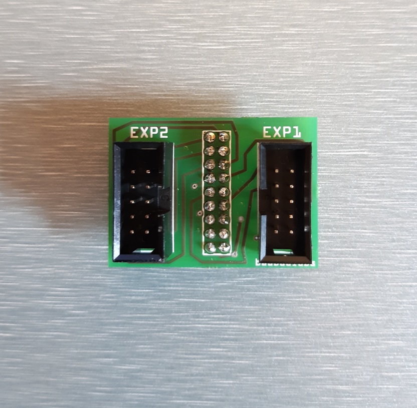
I only had to make a PCB with a 18pol. connector (mainboard) to two 10pol. connectors.
After this i had to update my firmware, because to pinning wos wrong.
Arduino boards have a pinmapping. Just look at google.
Im very happy with this SD-Card function.
A big point wy i wont to print without PC is the unstable USB connection.
Quick question;
How do one connect the LCD to the existing K8200 controller-board? - or do one have the use the “Arduino MEGA 2560 R3” board with “SainSmart 3D Printer controller 3D Printer Control Board Ramps 1.4” and the LCD with SDcard reader instead?