I have been eagerly awaiting the release of the K8206 extension kit for the K8200 (http://www.vellemanprojects.eu/products/view/?id=431478) which doubles one axis of the printer to provide a 200mm x 400mm print area and replaces the heated print bed with an unheated BuildTak surface.
Unfortunately, I have a project that could not wait for the official kit to arrive. (As of this writing, the K8206 kit is available in Europe, but I am told it won’t be available in the United States until around the new year.) So I decided to stretch my printer without using the kit, instead using a 200x300 heater board that I purchased on ebay.

Teaser photos for the K8206 stretch kit show that only a handful of parts need to be replaced. Conceptually it is as simple as extending the two side rails of the frame base, extending the two steel rails for the carriage, and lengthening the drive belt accordingly.

But it isn’t quite that simple. In order to minimize the physical modifications, the X-Y table must be turned 90 degrees (Y becomes X and vice-versa) so that the 200mm carriage assembly can remain intact. This means that the electrical harness needs to be rewired to accommodate the new range of motion. Finally, the actuator for the limit switch must be relocated/extended by about 50mm, to accommodate the longer print bed.
Mechanical Assembly:
The X-Y table must be turned 90 degrees, meaning that the rail and motor mounts must be moved from the (to-be-replaced) side rails onto the front/rear rails.
I replaced the two frame sides and the two guide rails with longer ones. A good rule of thumb is to get rails that are twice the length of the print area, but because I did not modify the carriage I could probably have gotten by with a 500mm - 550mm rail dimension instead of 600mm. I used “2020” slotted aluminum which is not an exact match for the stock used in the K8200 frame, but which seem to be compatible. I actually did not notice the mismatch until after I had rebuilt the frame.

I did not measure the length of the new belt. Instead, I cut it to length after it was installed in the printer. I specify a 1500mm T2 belt (as supplied with the K8200 kit) but you probably only need about 1200mm for this modification.
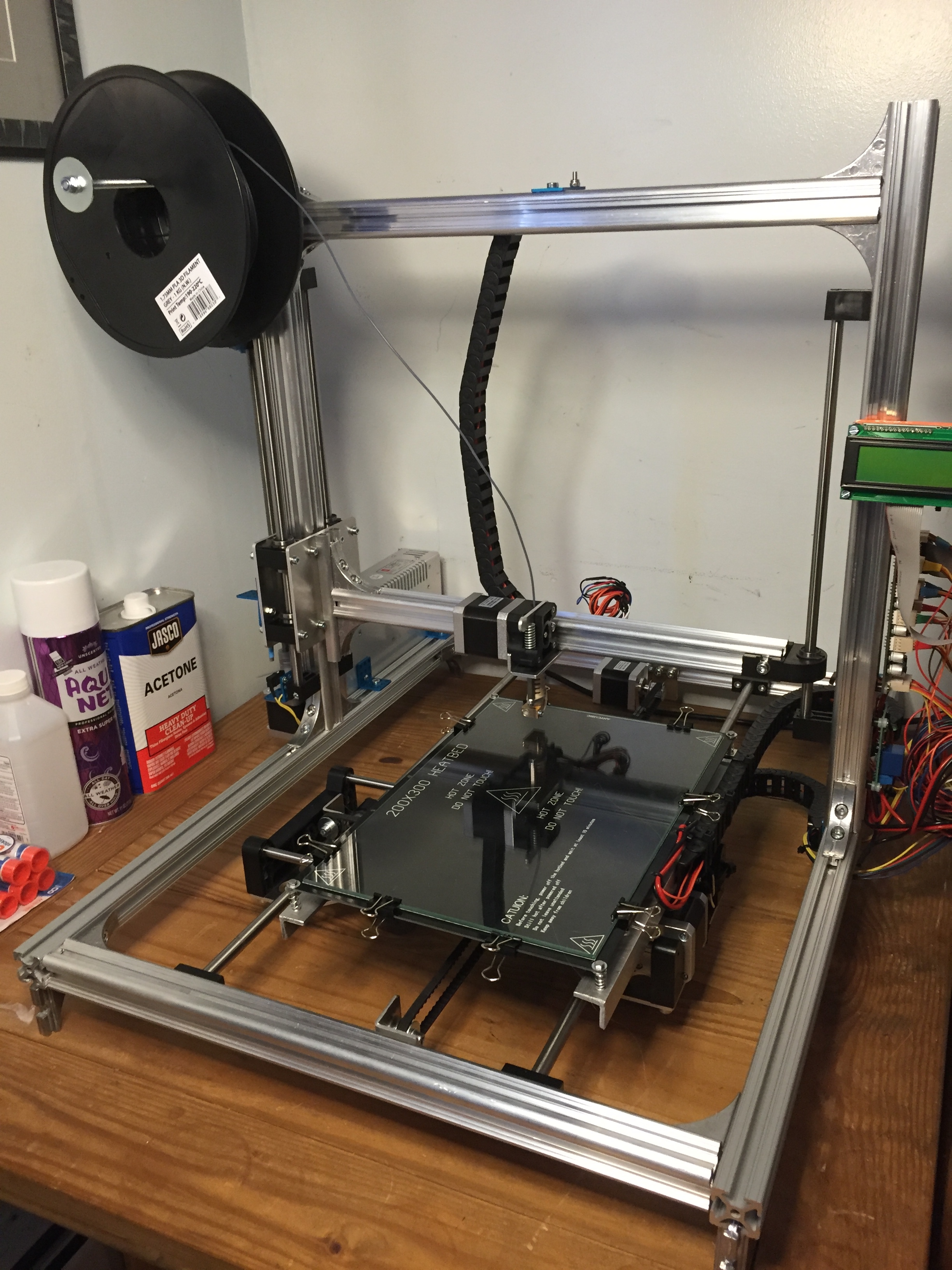
To mount the larger print bed, I extended the existing bed plate with a pair of angle aluminum rails. I tapped the PCB mounting holes with threads and added springs to make bed leveling easier. The new bed is centered over the existing bed plate, with ~ 50mm of overhang on the front and rear.


In this setup, the bed heater PCB doesn’t have much support and will warp. I used binder clips to clamp a 3mm borosilicate glass plate onto the top of the PCB, which seems to provide better rigidity. I will probably add a (non-conductive) support plate beneath the heater to further guard against warping of the print surface and insulate against heat loss.
The pictures of the K8206 kit show the stepper for the Y axis (former X axis) mounted to the front edge of the printer frame. I chose instead to mount this motor to the back of the printer for a cleaner look, as well as to keep the wiring shorter and more manageable. This means the motor direction will need to be reversed in the firmware.
The K8206 kit also appears to include a plastic bracket to change the mounting location of the limit switch for the extended axis. This is to ensure that the limit switch can be properly adjusted for the new table size/origin. I substituted some metal brackets from a robotics kit to extend the limit switch actuator.

Electrical:
The physical modification of the printer frame was straightforward, but the wiring harness needed to be almost completely rebuilt. The wiring to the X, Y, and Z motors and end stops all needed to be lengthened to accommodate the larger frame and new geometry. I used a mix of 22AWG and 18AWG wire instead of the stock ribbon cable.
The heated PCB can be operated at either 12V or 24V. Because the new heat bed draws 140 Watts, an upgraded power supply is required. I opted to run the bed at 12V, which allows me to run the entire printer (heaters and electronics) off of a single, 360W switching power supply.


I am using an external relay to switch the bed heater, as I doubt the controller board can switch that much power without overheating.

I had to acquire a thermistor for the heat bed PCB because the bed I bought on ebay did not include this critical part. I used the standard NTK 100K thermistor that is used in the original kit. If you use a different thermistor, make note to set the right value in Configuration.h so the controller uses the right temperature curve.
I had some difficulty routing the wiring from the X-Y carriage to the frame. I chose to run the bed heater and thermistor wires directly to the frame instead of to the bottom of the carriage, as the original K8200 design does. I splurged for plastic wire guides to help keep the harnesses from interfering with the limit switches and belts.


I also stumbled onto an inexpensive way to protect and hide the wiring harness. I pulled some heavy clear plastic out of the recycling bin and cut it into strips about 1cm wide. I then tucked the runs of wire into the channel in the aluminum 2020 frame and pushed the strips of plastic in to cover the wires and hold them in the channels. The result is very tidy, and the price is perfect.


Firmware:
With the machine rebuilt and the harness rewired, the last step is to update the firmware. Open Marlin firmware in the Arduino 1.0.4 IDE, and edit Configuration.h. Change the print area to the new size:
// Travel limits after homing (units are in mm)
#define X_MIN_POS 0
#define Y_MIN_POS 0
#define Z_MIN_POS 0
#define X_MAX_POS 200
#define Y_MAX_POS 300  // was: 200
#define Z_MAX_POS 220  // was: 200
Test the motor movement and reverse the direction of any axes that do not move in the right direction, by setting INVERT_X_DIR, INVERT_Y_DIR, or INVERT_Z_DIR accordingly.
Finally, change printer parameters in Repetier/Slicer so it knows it has more usable print volume.
Everything looks good so far… First test prints are underway.
With a modest investment and a couple weekends of hacking, I now have a larger print area, and increased confidence in my ability to modify this fantastic printer.
The open, “hackable” design of the K8200 once again shows its strength. Kudos to the folks who designed the K8206 kit and proved that this is possible. I will show my support by purchasing the kit when it is available here.
Hey Doc,
That is one nice build the instructions are good as well
Do you have a link where you found the bed at?
Thanks
I got the PCB and glass both from the same seller on ebay. Here are the links to what I bought, but there were many other sellers with the same items.
PCB: ebay.com/itm/282106994831?_t … EBIDX%3AIT
Glass: ebay.com/itm/282013521791?_t … EBIDX%3AIT
The printer is working very well. I just uploaded a design for a set of clips to hold the glass onto the heater PCB. Much better than binder clips!

thingiverse.com/thing:1987898
Great writeup, congratulations on your mod!!
