K8200 with Dual Extruders

I have successfully upgraded my K8200 to have dual extruders. I used a pair of K8203 Direct Drive Extruder kits and an Arduino MEGA2560 with a RAMPS 1.4 shield to replace the controller. It was a major upgrade and could have gone more smoothly if some of the vitals were better documented, but it is now working.

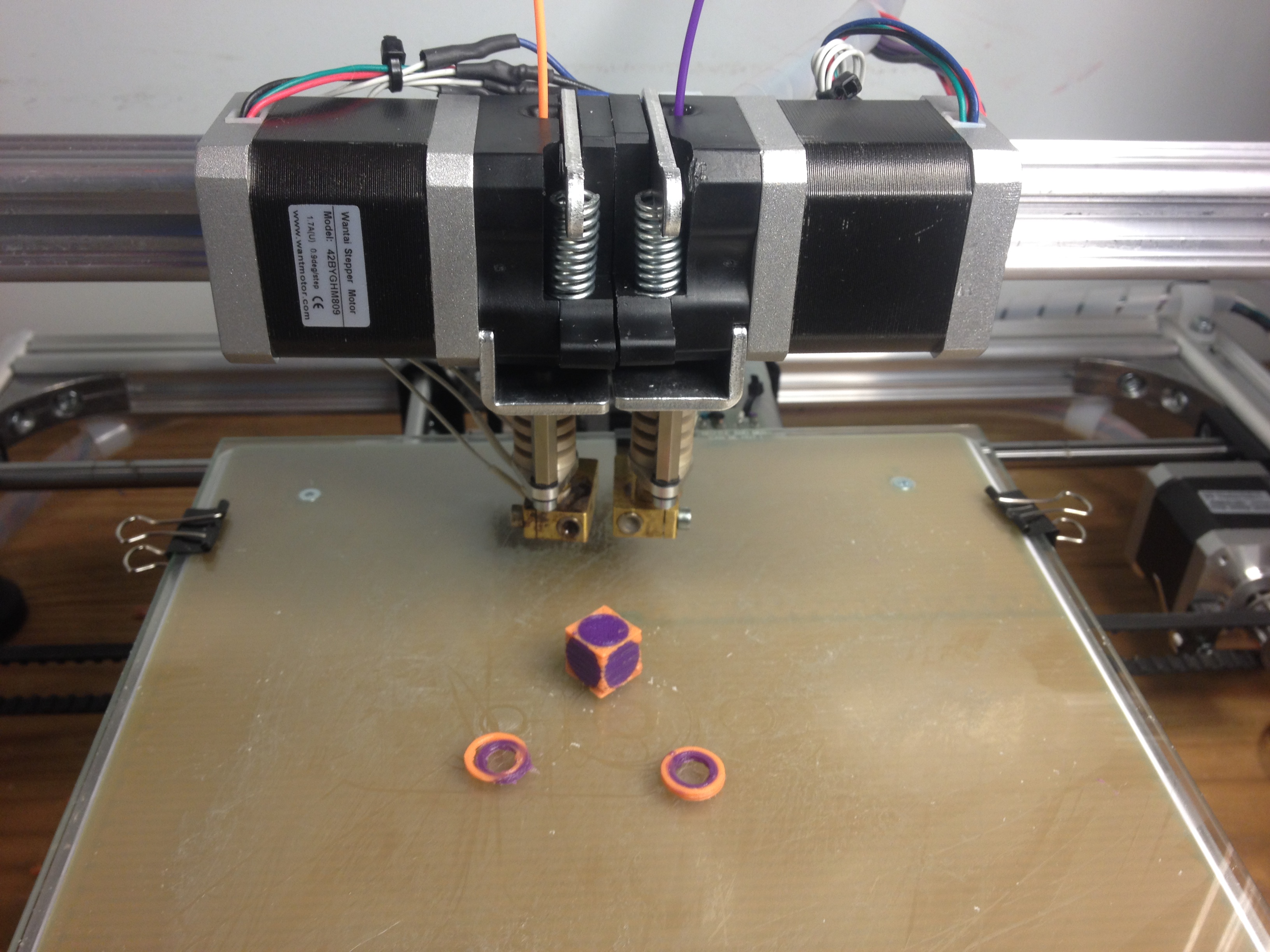
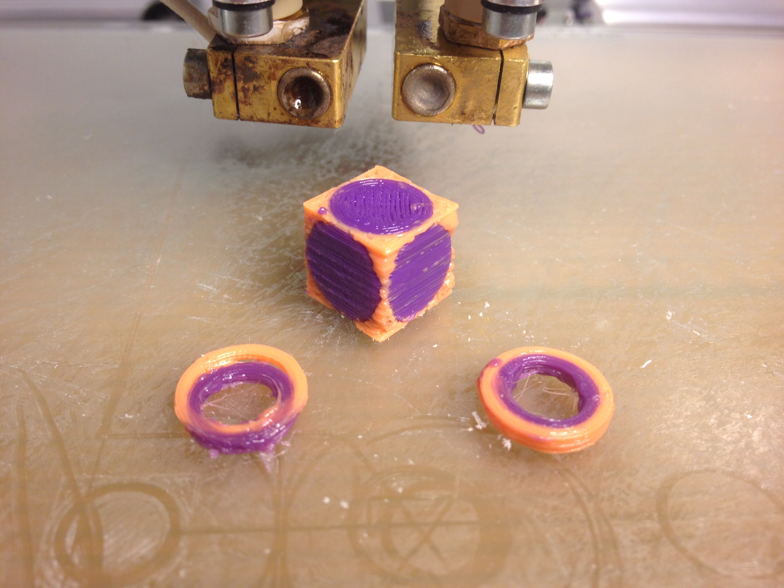
As you can see from the test prints, the calibration between the two heads is pretty good. The rings on the left were a test print with rough estimated head offsets which was used to measure the actual offset.

I think the filament is not priming well after being retracted while a head is inactive. I will try some larger prints next to see if the flow evens out with more run time per layer.

I will be documenting how I did the upgrade here in this thread. I know some other people on this forum have also upgraded to dual extruders, so please jump in and share your experiences as well.

Why Dual Extruders?
I want to print objects with dissolvable support material, or using multiple colors of filament. I am also looking to the day when alternate materials are more widely available. Flexible materials, filament containing wood or metal particles, and electrically conductive materials are all becoming more common.

Why not Dual Extruders?
Take the headaches of calibrating the z axis, loading filament, cleaning the print head, clearing jams, and priming nozzles. Now double the probability of a disaster at any step. Be ready to spend even more time dialing it in than you did when you built it the first time.

Also note that the process of designing and slicing models for multiple extruders is more difficult and time consuming. It disrupts the relatively simple download-slice-print cycle. Not all of the printer software fully supports multiple extruders.

For me, one other concern was that the direct drive extruder kit uses 1.75mm filament instead of the 3mm stuff that I had already stockpiled. I was happy with the performance of the original kit, and did not want to lose print speed for simple print jobs. So I decided to leave my original K8200 intact and build a second kit with the dual extruders.

Miscellaneous Upgrades
My K8200 was built with all the basic upgrades. These are all great improvements, and I strongly recommend doing the first few at least. But they are completely independent of the dual extruder upgrade, and are not the main point of this post.

  • GP8200 Borosilicate bed plate - flat, smooth surface whether heated or not.
  • 24v bed heater power supply switched by relay - fast heat times, hotter bed temperatures, less strain on controller power supply
  • K8204 Z axis upgrade kit - smoother z-axis movement with less banding.
  • 0.9-degree stepper motors (this was an accident, but I think it has benefits.)

Materials
To upgrade to dual extruders, you will need the following:

  • (2) K8203 Direct Drive Extruder kits
  • (1) 42BYGHM811 1.8-degree stepper motor (should match the motor on your existing extruder)
  • (1) Arduino MEGA 2560 controller
  • (1) RAMPS 1.4 shield for Arduino
  • (15) 2-position PC jumpers
  • misc. wire and connectors
1 Like

Mechanical Assembly
The K8203 kit includes duplicate parts so that the extruder can be built in left-hand or right-hand orientation. Assemble both kits, one in each orientation. This will make it possible to mount the nozzles very close to one another on the cross-arm - about 25mm apart in my build.

The nozzles on this extruder tend to leak, so I added a loop of teflon (plumber’s) tape around the brass threads before installing the nozzles. The nozzles should easily hand tighten - don’t cross-thread them. Try to get the lengths of the hot ends to match each other.

Mount the two extruders as close together as possible. The shorter the distance between the nozzles, the more effective volume you will have for printing.

Check the height of the two nozzles above the print bed by sliding a sheet of paper on the bed while rotating the z axis motor by hand. The nozzles should both pinch the paper onto the bed at the same height, or as close as you can possibly manage. Bend the metal brackets up or down until the nozzles are at the same height. Don’t worry if this puts them out of line with one another - you will set the x and y offsets when you modify the firmware.

Save the extra parts from the K8203 kits - especially the small funnel-shaped parts. These can jam easily, so you may find yourself swapping them out occasionally.

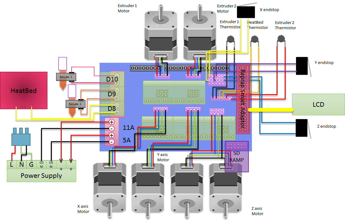
You will need to run wires for the second extruder motor, hot end, and thermistor back to the controller. The same connectors can (mostly) be used on both the Velleman controller and the RAMPS board. The end stop switch connectors are spaced differently, but I was able to use connectors that allow me to swap between the Velleman and RAMPS controller boards at will. This is useful for isolating whether a problem is happening in the controller or in the hardware.

At this point you can test the mechanical operation of everything by connecting one extruder at a time to the original Velleman controller. (EDIT: You may need to update your firmware to support the 8203 before you can print!) You should be able to get clean test prints out of either extruder. If everything looks good mechanically, you are ready to upgrade the controller and firmware.

1 Like

Electrical
The RAMPS board attaches to the top of the Arduino controller. Be careful when aligning the pins. The bare RAMPs board has rows of headers for the installation of the stepper drivers. Underneath each driver is a set of three jumpers for micro-step selection. Put a jumper block across each pair of jumpers (three per stepper) to select 1/16th microstepping.

Next, carefully remove the x, y, and z stepper drivers from your Velleman controller, and insert them onto the correct locations on the RAMPs board. Check that the DIR and GND pins on one end of the driver card match up with the DIR and GND on the header. Insert the stepper drivers that were included with the K8203 kit into the E0 and E1 slots on the RAMPS board, again making sure to align the DIR and GND pins correctly.

I was able to use the original motor connectors, but did have to change the thermistor and endstop connectors so they would fit on the RAMPs board. I followed the documentation for the RAMPs board when connecting everything. Be careful to connect the extruder and bed heaters to the correct outputs. I found conflicting information online, but the bed heater goes to D8, the first extruder goes to D10, and the second extruder goes to D9.

When you can apply power to the board, adjust the x, y, and z stepper drivers to a 0.55v control voltage, and set the E0 ad E1 drivers to 0.8v.

I have been able to power the Arduino+RAMPS off of the original 15v Velleman power supply by making a Y-connector to attach the ps output to both power input terminals. If you add a separate bed heater supply then this should have no trouble. However, you may wish to upgrade the power supply if the voltage droops under load.

1 Like

Firmware
I initially tried to modify the Velleman-supplied Marlin firmware, and it probably would have worked. But before I finished the project, I decided to pull the latest version of the Marlin firmware and configure it afresh. As much as the kits are excellent, I do wish the Velleman documentation was more complete. I had to read the firmware to extract the few values that needed to be changed to support the various upgrade kits.

Only Configuration.h needs to be modified before the firmware is installed onto the Arduino. Because I had installed several upgrades, I needed to make a number of changes not directly related to dual extrusion.

The dual extrusion changes are to set the MOTHERBOARD controller type and configuration for RAMPS 1.4 with two extruders and a bed heater - BOARD_RAMPS_14_EEB. I had to set the number of EXTRUDERS to 2 and un-comment the EXTRUDER_OFFSET_X and _Y arrays, which will be set with numbers measured on your printer. Start with an offset of 25mm for X and 0 for Y - you will calibrate this later.

[code]#define MOTHERBOARD BOARD_RAMPS_14_EEB

#define EXTRUDERS 2

#define EXTRUDER_OFFSET_X {0.0, 25.50} // (in mm) for each extruder, offset of the hotend on the X axis
#define EXTRUDER_OFFSET_Y {0.0, -0.75} // (in mm) for each extruder, offset of the hotend on the Y axis
[/code]
Set the DEFAULT_AXIS_STEPS_PER_UNIT for X and Y to 64.25, and for Z to 2133.333 if you used the K8204. Set the fourth axis value to 150 for the K8203 extruder - and note that this same value is used for both extruders. If you used 0.9-degree steppers instead of the stock 1.8-degrees, double the corresponding STEPS_PER_UNIT value for that axis.

#define DEFAULT_AXIS_STEPS_PER_UNIT   {64.25, 64.25, 2133.333, 150}  // K8203+K8204

Because I started with the generic Marlin branch, I also had to re-apply a few changes to match the K8200 specs. I had to set the TEMP_SENSOR types to 5 for both extruders and the bed. And I had to set the default speed and acceleration values to those set by Velleman. You may also need to set the INVERT_X_DIR, INVERT_Y_DIR, INVERT_Z_DIR, INVERT_E0_DIR, and INVERT_E1_DIR to match the wired direction of the motors. (NOTE: My bed heater is currently getting very hot so I may have this wrong.)

#define TEMP_SENSOR_0 5 // Was 1 #define TEMP_SENSOR_1 5 // Was 0 #define TEMP_SENSOR_2 0 #define TEMP_SENSOR_3 0 #define TEMP_SENSOR_BED 5 // Was 1

#define DEFAULT_MAX_FEEDRATE {500, 500, 5, 500} // (mm/sec) #define DEFAULT_MAX_ACCELERATION {9000,9000,100,10000} #define DEFAULT_ACCELERATION 1000 // X, Y, Z and E acceleration in mm/s^2 for printing moves #define DEFAULT_RETRACT_ACCELERATION 1000 // E acceleration in mm/s^2 for retracts
Once all changes have been made, verify that the firmware builds without warnings or errors and load it onto the Arduino. (You will most likely adjust some calibration values and repeat this step, so don’t close the Marlin project in the Arduino IDE just yet.)

IMPORTANT: Any time you make changes to the firmware, you will want to reset the EEPROM settings, otherwise the changes may not take effect and the printer may behave erratically. You can use the printer control panel to first send an “M502” command, followed by an “M500” command to restore firmware defaults and write them into EEPROM memory, respectively.

EDIT: Here is the link to the Marlin git repository that I used: github.com/MarlinFirmware/Marlin/tree/RC/Marlin
1 Like

Calibration
Start Repetier and edit your printer configuration to specify that you have two extruders. Now connect to the printer as usual and make sure you can control all three axes of movement and that all endstop switches work. Make sure you can (briefly!) turn on the heaters for both extruders and for the bed, and verify that the correct thermistor is associated with each heater or you may melt things. If all looks good, heat the extruders and load filament to verify extruder direction.

If anything needs to be corrected, modify Configuration.h and re-load the firmware. And don’t forget to M502/M500 to reset the EEPROM!

At this point, you should be able to level the bed and print a single-color model; the primary E0 extruder will be used by default. You could also print on the secondary extruder with a slight tweak to your Repetier settings, but you will be eager to get on to dual printing.

To slice two materials, you will need to run Slic3r in stand-alone mode. You will also need a pair of .stl files to print - one for each extruder. I use OpenSCAD to design my models, so it is not too hard to difference the two materials to save a pair of .stl. Under Slic3r’s File menu, choose to “Combine multi-materal stl files…” and select both files. Then drag the resultant .xml file back into Slic3r and Export G-Code.

To calibrate my printer, I created a model of two short, nested rings. I was able to measure the error on each axis and adjust the values for EXTRUDER_OFFSET_X and _Y until the alignment was perfect.


thingiverse.com/thing:1295288

As a final test, I created a truncated sphere-in-cube model and printed it.


thingiverse.com/thing:1294871

The results are not perfect, but not a bad start. I am using 2mm filament retraction for the inactive head, but I think this may be a bit much. There is no dripping happening, but the nozzles aren’t well primed after the change-over. This may be less problematic when I print larger models with more continuous time on each nozzle.

1 Like

To-Do
Adding the second extruder heater means that there is no longer a power output to run the cooling fan. The Arduino firmware is programmed to toggle an IO pin (D4) to control the fan, but I need to wire up a MOSFET to actually switch it. So I am running without a fan for now.

I also have not yet wired the K8201 stand-alone controller up to the RAMPS board, although it is enabled in the firmware. The only thing stopping me is to find a robust method for cabling the 8201 to the RAMPS. I’ll document that here, once I get to it.

Conclusion
It is still very early to tell, because I am just starting to print models with the new setup. I am pleased with the improved quality of the upgraded printer due to smaller nozzle size and increased stepper resolution. And dual extrusion print jobs are definitely more complicated to design, slice, and run.

Now the fun begins…

Because this project is reliant on the K8203 Direct Drive extruder, I should link the following post from Fitchie: viewtopic.php?p=79127#p79127

The takeaway is that the DRV8824 stepper drivers that come with the extruder kit will run at 1/32 microsteps, but are much happier running at 1/16th microsteps. (Really!!!)

To change the microstep resolution on a RAMPS board, remove the stepper driver board for each extruder and remove the MS1 and MS2 jumpers, leaving MS3 connected. Then edit Configuration.h to reduce the STEPS_PER_UNIT for the extruders by half (from 150 to 75) before reflashing the Arduino and resetting the EEPROM values.

#define DEFAULT_AXIS_STEPS_PER_UNIT   {64.25, 64.25, 2560, 150/2}  // default steps per unit for ultimaker

That thread also has great information about replacing the stepper drivers for X and Y with DRV8824’s, effectively doubling the resolution on both axes, resulting in smoother prints.

I thought I would share my latest dual-extruder creation - a Minecraft Ore night light that uses natural PLA as a diffuser for the LED inside.

thingiverse.com/thing:1579110

1 Like

Looks very nice! And really good job on the instructions! There should be a “Guides” subforum in this forum to help people upgrade their printers without having to ask the same things over and over again. But really good job!

1 Like

As a follow-up, I did eventually figure out how to wire the VM8201 LCD Display / SD Card Reader to the RAMPS 1.4 board. I started to document it, although I had trouble getting the post to format correctly with the new forum software.

I’ll link it here, for completeness.

1 Like

can you sent me pics of the board en the build i want to bild it too