K8016 has 8 digital 8-bit outputs. How this digital data transfers through these outputs? I mean, I understand that this is serial data, but how can I synchronize with it. How can I know that the data is being transfered?
To be more clear - I need to connect Shift-register to convert it to a parallel data. What my options are?
[quote]K8016 has 8 digital 8-bit outputs.[/quote]The K8061 has 8 digital 1-bit outputs.
Using this function, OutputAllDigital(CardAddress, Data), the byte ‘Data’ is output to the 8 digital outputs in parallel mode.
Using these functions you can set / clear individual bits of the 8 bit output:
ClearDigitalChannel(CardAddress, Channel)
SetDigitalChannel(CardAddress, Channel)
Thank you for respond. But the main question remains for me - how can I sychronize data transfer to an outboard device or I.C? And what data rate can be expected?
The first idea that comes into my mind is to use one bit as a data, and the other as a clock, just like i would normally do with a PIC. Am I correct or is there more prefessional solution?
[quote]But the main question remains for me - how can I sychronize data transfer to an outboard device or I.C?[/quote]You can send first the data and then the clock to the digital outputs.
[quote]And what data rate can be expected?[/quote]The general response time is 4ms per command.
[quote]The first idea that comes into my mind is to use one bit as a data, and the other as a clock, just like i would normally do with a PIC. Am I correct or is there more prefessional solution?[/quote]I think this solution is OK.
I’ve managed all issues and questions. Everything is working. Almost.
I’m trying to connect K8061 with a LED driver MAX7219. This is a well-known chip and there are quiet a few samples of source codes. First of all I’ve tried to establish my own code. I failed to do it quickly (i thought so!).
Then I took a code from the internet - the same problem - the LED driver connection is unstable. Well, at least that’s what I think it is.
There are sometimes succesful commands and LED driver lightens the way I want it. So that gives me thoughts that the device, connections and code is correct. But in 90% of all time I fail to see anything. Sometimes the digit blinks for a fraction of a second, sometimes nothing at all happens.
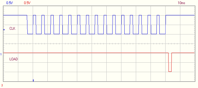
The way I do it - Output 1 goes for a CLK signal. Output 2 - is a Data. And Output 3 is a Load signal (for latching the serial data in MAX7219). First of, I set the Data bit, then i set CLK to high and then back to LOW. I send 16 bits this way and then I set LOAD bit to HIGH, and then back to LOW.
With these ways I initialize the max7219 chip, i think I do it correctly, because it works sometimes
So the problems are in the timings of signals. I use the code as if I would use it in some PIC. Probably there are some diferences in how I should use it with your controller???
Please give some ideas of possible solutions. Any information is appreciated.
I try to use your card to test and simulate the work of my digital devices so it’s every important to have an adequate connection and data transfers.
The digital outputs of the K8061 are open collector outputs. You have to add the pull-up resistors from each output you are using to the external power supply plus (+) pole.
hey i know that ofcourse i’ve added pul-up resistors. otherwise i wouldn’t get anything at all. The thing is that i don’t get reliable data transfer. sometimes max7219 does what i want and most of the times it doesn’t (the digit might just blink for a fraction of a second).
Well, the truth is I haven’t noticed any differences when I was adding some NOP commands or even dummy loops with some math just to make some delay. According to cycle datasheet of MAX7219 there is no need in some sophisticated synchronicity. The data is being read once the CLK signal is high. So what I do is first of all set the data bit, then set the CLK to high, and then back to low.
Perhaps if you could provide some data about time response to commands of K8061 or something that to help me in time calculations. That would be great.
On the other hand, I can give you the part of the source code that I use (C++) and maybe that could help finding the mistakes? Or is there any circuit mistakes? Maybe wrong pullup resistors nominals. But I’ve measured hi and lo levels and it gave me very stable levels of 0.6V in LOW and 4.5V in HIGH.
I can check and test your program.
You may give only the section where the data is sent to the K8061.
I’ll run it and check and record the output sequence from the K8061 digital outputs.
static void MAX7219_Write(unsigned char reg_number, unsigned char dataout)
{
LOAD_1; // take LOAD high to begin
MAX7219_SendByte(reg_number); // write register number to MAX7219
MAX7219_SendByte(dataout); // write data to MAX7219
LOAD_0; // take LOAD low to latch in data
asm(“nop”);
LOAD_1; // take LOAD high to end
}
//--------------------------------------------
// MAX7219_SendByte()
// Description: Send one byte to the MAX7219
// Arguments : dataout = data to send
// Returns : none
//--------------------------------------------
static void MAX7219_SendByte (unsigned char dataout)
{
char i;
void MAX7219_Write(unsigned char reg_number, unsigned char dataout)
{
LOAD_1; // take LOAD high to begin
MAX7219_SendByte(reg_number); // write register number to MAX7219
MAX7219_SendByte(dataout); // write data to MAX7219
LOAD_0; // take LOAD low to latch in data
LOAD_1; // take LOAD high to end
}
//--------------------------------------------
// MAX7219_SendByte()
// Description: Send one byte to the MAX7219
// Arguments : dataout = data to send
// Returns : none
//--------------------------------------------
void MAX7219_SendByte (unsigned char dataout)
{
char i;
for (i=0; i<8; i++)
{
CLK_0; // bring CLK low
if (dataout & 0x80){
DIN_1;
}
else{
DIN_0;
}
dataout=dataout<<1;
CLK_1; // bring CLK high
}
}[/code]
The timing seems to be OK too.
Everybody! This is a miracle! I have solved the puzzle. Thanks VEL255 for helping me out, your comments indeed helped me to understand some stuff. BUT… all my problems were because of something else.
The moment I’ve added a small condenser to my supply chain - everything becamse perfect. I’ve realized it only when i’ve assembled a new schematics using a standalone digital controller with a program in it. And when I saw that the result is the same bullshit - I’ve started finding another way out. So, correct supply was the answer!
Never forger to insert condensers in the condensers!