hello
I want to connect on each digital output, a relay working via a transistor that needs 5 v to works.
How can I do that?
Read a lot of things on this forum but do not really understand how to do
thanks
Eric
hello
I want to connect on each digital output, a relay working via a transistor that needs 5 v to works.
How can I do that?
Read a lot of things on this forum but do not really understand how to do
thanks
Eric
Is this 5V the coil voltage of the relay?
How big is the coil resistance?
Depending on these values you can drive the relay either directly from the digital outputs of the K8055 card or via external power transistors.
In any case you need an external voltage source to energize the relay coils.
Hello
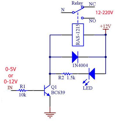
Relay is a RAS-1215 supplied by +12v and negative is controlled by a transistor BC639
I have to put 5v or 12 v to this transistor to connect negatif to ground and then open or close the relay.
I can send you a draw if I have your email address
thanks
eric

There are two alternative solutions.
In both cases you have to do some modifications to your relay circuit.
Either add pull-up resistors from the IN to +12V
Hi!
I designed a similar “relay switch” with transistors, but for some reason it goes “on” when de digital output of the K8055 is “off”, and “off” when the digital output of the K8055 is “on”. To check whether or not I made a mistake, I built the one in on this page. Result: Same problem.
Does anyone know why this might be? Thanks in advance!
PS: I know that I am responding to an older post, but thought I should post it here… (Am I right?)
[quote]I designed a similar “relay switch” with transistors, but for some reason it goes “on” when de digital output of the K8055 is “off”, and “off” when the digital output of the K8055 is “on”. To check whether or not I made a mistake, I built the one in on this page. Result: Same problem.[/quote] You didn’t make any mistake. It is normal that the transistor connected to the output of the K8055 inverts the control signal to the relay.
If the relay is directly connected to the output of the K8055, then it is activated when the output is “ON”, i.e. the digital output of the K8055 is low (the internal transistor is conducting).
The external transistor is not conducting in this case. The base of the external transistor is pulled down by the output of the K8055. This is the cause to the inverted operation.
Thanks for the quick response!
Using your response, I found the solution to my problem in the addition of another inverter (one transistor and two resistors) to my system. Now it goes “ON” and “OFF” at the right moment. Much safer if you ask me…
It’s nice that you found a solution by adding one more inverter there!