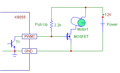
Trying to drive a small DC motor using the K8055’s PWM function and a MOSFET. So far have had limited success, but I would like to know the “correct” way to do it if possible. Seems that the K8055’s PWM output drives low rather than high, which is a slight obstacle for using an N-channel MOSFET.
Here is the circuit I am using with my MOSFET, could anyone please tell me the correct way to wire this up?
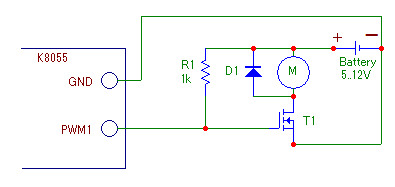
Thankyou for the help. I now understand a little better what I need to do. The updated diagram is not, I feel, quite as user-friendly as the one I first saw.
The updated diagram assumes the motor is to turn in one direction only (diode presence for back e.m.f. protection?). I would use a miniature DPDT latching relay driven from two amplified digital outputs of K8055 to allow reversal so would you show this facility in your diagram, please? Would a further relay be required to STOP the motor, or would minimum voltage supply do this without one being necessary?
I wish to use:-
0.25A 5vdc supply as this will more than accommodate the stall current of any motor I would want to use in ‘T’ gauge.
0.25A 9vdc supply as this will more than accommodate the stall current of any motor I would want to use in ‘Z’ gauge.
0.5A 12vdc supply as this will more than accommodate the stall current of any motor I would want to use in ‘N’ gauge.
0.75A 12vdc supply as this will more than accommodate the stall current of any motor I would want to use in ‘TT’ gauge.
1.25A 12vdc supply as this will more than accommodate the stall current of any motor I would want to use in ‘H0’ gauge.
2.5A 12vdc supply as this will more than accommodate the stall current of any motor I would want to use in ‘0’ gauge.
I would want to see circuit diagrams for all of these scenarios, please; alternatively, one diagram with appropriate labels.
All of this information, if supplied, may be published in ‘THE MERG JOURNAL’ - a U.K.-based non-profit organisation. Full accreditation would be given to Velleman Inc. in the text as the objective is to bring to the attention of club members the model railway application of K8055/VM110 and K8061/VM140 modules. This would increase the sales of these products as a by-product of user enjoyment.