I want to make a IR proximity detection device and control it with the K8055.
I want to use this design http://ikalogic.com/ir_prox_sensors.php.
Sender
I’m thinking maybe i can control the sender with the digital outputs or the PWM. I don’t understand the PWM very well so i’m not too sure how it would work. If any of those aren’t possible then i could use a 555 but knowing the exact frequency for the sender would be problem.
Reciver
For the receiver maybe the digital inputs would work. The problem is i don’t understand how to make the program read the input as a waveform instead of just pulses. Also i read on the forums somewhere that the PWM frequency is higher than what the K8055 input can read, so i’m not sure how that would work.
Any help on how i can go about this or any information on understanding the digital input for the k8055 is greatly appreciated.
The circuit im talking about. D1 in the receiver circuit is the IR receiver.

I am interested in such project too. But in the link you posted there is a note that it was tested at 3kHz frequency.
PWM output has fixed 23.4kHz frequency. I’m not sure what frequency can u get with the ADC,i mean with the digital outputs, maybe someone will know? I think that the digital frequency should be much lower, because it uses the usb connection which is 10ms response time, since PWM is hardware related and digital out gets each signal from computer, right ? so total send and receive should take 20ms and that’s a frequency of 50hz…  realy?
Then the problem is here that the sending IR has 3kHz frequency, at least it was tested at such frequency, and i think the higher the frequency the better the accuracy. but the receiver should work at higher rate,to have good accuracy. Though K8055 input can count only up to 2kHz frequency, and that’s not enough.
Hmm i found this on the same site its seems much easier. The ir sensor itself only picks up - 40khz squarewaves. So no reading code is needed its all done by the ic in the receiver. Maybe the PWM could be used to make the sender frequency, but i dont understand how it works it goes from 0 to 255 so how do i know what frequency its at? A 555 can be used to create the signal to but finding exactly 40khz could be a problem.
The ir receiver im using is this one. http://www.rapidonline.com/Electronic-Components/Optoelectronics/Infrared-Devices/Infrared-photo-module-38kHz/77753
The link to the site http://www.ikalogic.com/ir_prox_sensors_40khz.php
The circuit 
I’m thinking my receiver shouldnt need a perfect square wave but i have bought the logic chip just in-case. (unless theres a way to make the wave through the k8055). After that its as simple as connecting the receiver to the input.
Its a shame my htc func gen app can only go up to 20khz 
You can check PWM here http://en.wikipedia.org/wiki/Pulse-width_modulation
PWM is basically what it says - pulse width modulation. You have let’s say +5V signal and 0V signal. So if u will make 50% of the time to go 5V and 50% of the time 0 volts, so you will have 2.5V signal. But K8055 PWM is active low, it means that if u set dac 1 to 0, so the PWM output will be 5V, and at 255 position of DAC 1 the PWM will output will be 0 volts. So by changing the duration of each High and Low signals you can get whatever voltage you need.
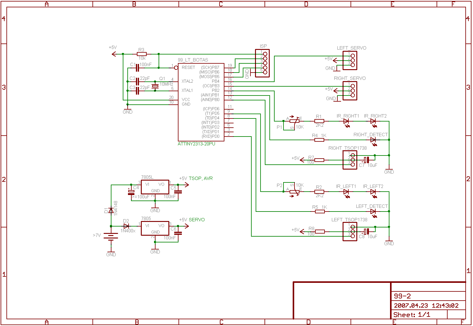
If you need just a simple detection, is there object or not, it should work. However there is another way of using the microcontroller. Check this sample circuit. It for robot distance sensing.
There are two sepparate parts of detecting the object, left and right. So you would need only 1 part of the circuit from the right bottom. And it’s all about how you will program the microcontroller. You can get whatever you want. Eg. if microcontroller gets signal from TSOP that there is an object then… whatever you want.
Let us know if this project gonna work or not. You can get the square function with the K8055, i even found a program for this in this forum, look for it, but i believe that the frequency will be low… Though you can try it out.
I went and got a Arduino Mega board. Its a K8055 with more ouputs and a pic put together.
http://arduino.cc/en/Main/ArduinoBoardMega
for the ir detection I used 2 555 chips 1 for 38khz carrier wave another to modulate the wave.
the ir reciver module itself can be connected straight into the board with no addition circuitry.
The only problem is my IR module TSOP4838 only reads modulated signal and i want to read the input as a frequency so I can use 2 transmitters with only 1 receiver, so the problem is i suck at program and i’m having difficulty making a frequency counter type program.
