Firstly, apologies if this has been asked before - a search and a hunt through the forum didn’t yield anything that seemed to answer my question.
Please can someone tell me how to use the K8055 digital outputs to drive 4000 series CMOS logic ICs, for example the 4070 AND gates? (A cricuit diagram would be perfect!) My aim was that the 4070 would be powered externally, but if I wasn’t sure how the connections to the GND, Clamp and outputs would work to drive the logic gates.
The digital outputs and the PWM outputs are open collector NPN transistor outputs. There is no voltage coming out from these outputs.
You have to connect pull-up resistors from the digital outputs to the plus (+) pole of the external supply. Connect the negative pole of the supply to the GND terminal of the K8055 card.
The CLAMP terminal is needed for inductive loads only.
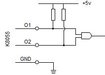
Before I completely mess things up, can I confirm that the circuit diagram below shows the correct arrangement to connect the K8055 digital ouputs to a logic gate…?
If this is right, doesn’t this mean that in this example, the inputs to the AND gate are the inverse of the outputs from the K8055 - i.e. when the output is high, the input to the AND gate will be grounded, and hence will be low?
Thanks for the help on this, and apologies if these are really basic questions - I’m on the electronics learning curve but hopefully progressing along it!
[quote]If this is right, doesn’t this mean that in this example, the inputs to the AND gate are the inverse of the outputs from the K8055 - i.e. when the output is high, the input to the AND gate will be grounded, and hence will be low?[/quote] You are absolutely right. The digital outputs of the K8055 are “active low” outputs. When set ON, the output transistor is conducting and the output is pulled down to GND.
You might want to use a higher voltage (10-12V) for the CMOS supply, they can get sluggish when operating at 5V–though this may not matter in your application…