Hi,
I have just posted this question to the forum -
- but I am not sure which group is best so if anybody in this group can help I would be grateful.
Cheers
Clive
Hi,
I have just posted this question to the forum -
Cheers
Clive
Here you go (option 2, option 1 would be somewhat complex and likely imprecise if implemented in the analog domain)…

You’ll need to make sure you ramp the motor speed down before changing the direction of rotation…
Thanks for that.
The circuit looks like a nice and simple solution.
I was starting to look at using an H bridge but that seemed more complex and also require two digital outputs.
[color=#FF0000]One more question[/color]: Do I need to connect anything to the “CLAMP”?
Regards
Clive
No need to connect to CLAMP.
The diode D2 is the clamping diode in this case.
If no D2, then you have to connect the battery plus (+) pole to the CLAMP terminal.
Hi, What is the RL1 component in this example?
The RL1 is the relay coil.
Thanks - RL - ReLay… makes sence  sorry for being thick!
Is it feasible to replace the relay with a transistor?
[quote=“seantaylor”]Thanks - RL - ReLay… makes sence  sorry for being thick!
Is it feasible to replace the relay with a transistor?[/quote]
With a single transistor and one i/o port NO, with an H-bridge and 2 i/o ports sure.

You said you wanted a simple way…
Hi there 
I have a similar problem: I’ve been searching all the day to get a motor to run using the PWM-output. I have an H-Bridge LMD18200 (http://www.national.com/pf/LM/LMD18200.html) with direction control but don’t know how to connect them to the K8055. As brake and direction I want to use digital outputs.
Hopefully you can give me an advise how to bring the PWM with my H-Bridge to work.
Thanks in advance
shyd
The LMD18200 seems to fit very well to use with the K8055.
Just connect the PWM pin to the PWM output of the K8055.
Connect the DIRECTION and BRAKE pins to the digital outputs of the K8055.
Add pull-up resistors to all these three pins. The pull-up resistors can be connected to an external voltage source not higher than 12V.
Thanks for your reply!
I just tried without the resistors, but no luck.
What exactly do the pull-up resistors? I would use the USB current to set DIR and BRAKE, what resistors would you recommend?
shyd
The digital outputs and the PWM outputs are open collector outputs. There is no voltage coming out from these outputs.
You can use 4k7 pull-up resistors to the +5V. (Any value 1k … 10k will do the job.)
Thanks a lot! Now it perfectly works! 
[quote=“cliffyk”]
[/quote]
Hi there! 
I have built this circuit, and it at least partly works - switching the Digital out on and off switches the relay…
trouble is, the motor doesn’t turn with the PWM output switched on - how do you switch the motor on? 
Tim
When the PWM setting is set to 0, the PWM output of the K8055 is not activated (i.e. open).
The transistor is getting base current via the resistor R1 all the time and the motor should run maximum speed.
When the PWM setting is increased from 0, the base of the transistor is pulled down a period of time by the K8055 PWM output. This reduces the motor speed. The motor is stopped when the PWM setting is 255.
Is the motor now all the time stopped?
Does the motor run OK if you bypass the transistor Q1 with a piece of wire?

I’m almost too embarrassed to say the transistor was in the wrong way round 
Still so much to learn!
Thank you for the description of how to use PWM to slow the motor to a stop though 
Tim
It’s nice to see that you got it working 
Hi all
i have a problem . i want conect the Vellemann K8055 to this Motordrivers.
watterott.com/de/Motor-Steue … 2PBF-24v20
i dont know how to connect and if i need some resistors etc.
could anyone give me a circuit how to conect??
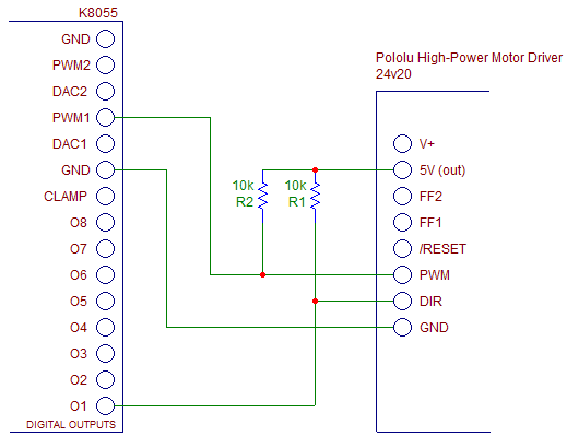
This circuit should work:

This is not tested, just designed based on this document:
pololu.com/catalog/product/759
A quote from the manual:
“[color=#000080]The logic connections are designed to interface with 5V systems (5.5 V max); the minimum high input signal threshold is 3.5 V, so we do not recommend connecting this device directly to a 3.3 V controller. In a typical configuration, only PWM and DIR are required. The two fault flag pins (FF1 and FF2) can be monitored to detect problems (see the Fault Flag Table below for more details). The RESET pin, when held low, puts the driver into a low-power sleep mode and clears any latched fault flags. The V+ pin on the logic side of the board gives you access to monitor the motor’s power supply (it should not be used for high current). The board also provides a regulated 5 V pin which can provide a few milliamps (this is typically insufficient for a whole control circuit but can be useful as a reference or for very low-power microcontrollers).[/color]”
Please note:
The PWM output of the K8055 is “active low”.
The motor speed is at the maximum when the PWM setting value is 0.
The motor stops when the PWM value is set to 255.
Thx for that
i will try out
