I’ve recently build the K8018 LED Cube, but it doesn’t seem to be working. The LED’s won’t turn on and the cube doesn’t connect to my computer. When the cube is plugged in, I can measure a voltage of around 300mV on the LEDs, but they don’t light up. I suspect there might be something going on with the ICs. Can anybody point me in a direction on how I can check if they are working ok? I’ve got a multimeter and an oscilloscope at my disposal.
I have tried to install the drivers on two PC’s and tested with two different cables, so I think the fault is somewhere on the side of the LED Cube.
But the second post you linked was very interesting. I tried to measure the Voltage on the LM137 ( which was 4,25V, should be 5V) and on Pin 20 of the main IC (Which was only 3.5V, should be 5V). So I think the fault could be somewhere on the power supply side of the board.
Just for the record, I used a 9V 3A power supply.
I also just checked all my resistors and diodes and they seem to be in working order.
Can anybody point me in a direction how I should go from here?
(as i understand “capacitors are used to address input noise and output transients” you smooth the Voltage)
Also from my understanding of the schematic when you plug the USB you have the LD1 LED3RL lighting ! is this your case ? is this LED OK ? not broken or inverted ?
Hoping you will find the solution to this mystery and tell us !
Thank you for your investigation into this issue, it’s much appreciated!
Ok so you’re right, 4,25V on the output should be fine! I also just check the PIC Data sheet and it says it needs an operating voltage of around 2V-3.6V (https://ww1.microchip.com/downloads/en/DeviceDoc/30009964C.pdf)
I can read 3,55V on the VDDCore Pin (Pin 20), so that should be perfectly fine.
That probably means voltage supply is ok. The LED also lights up while attached to the usb port. But the PC doesn’t recognize any device at all when plugging it in.
This is even more a mystery
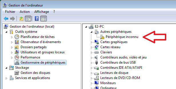
So USB pluged the LD1 is On, but the Computeur dont show any new devices under the System “Device Manager” ?
So from the diagramme : if the LD1 is “On”, the IC1 is alimented and connected … (except bad soldering or pin broken or bent for the pins
VDD physical 20 of the IC1,
(? GND) physical 8 and 19 ,
D+ physical 16 ,
D- physical 15 )
So if you have check this pins and connection between (usb port to IC1)
and check the right orientation of the IC1, and of the IC socket. ( yes the socket too one time i miss oriented one … dont just check the notch on the socket check on the PCB too)
I circle back to : You should see a new “unknown device” in your "device manager "
So you can install the driver
N.B. : I have a K8019 (that have a similar IC1) Windows don’t show any pop-up or notification, i have to look in the system device manager to find the “unknown devis” then right clic on it to install / update driver and give him the path to the driver …
and im out of idea for now !
Maybe after a good sleep …
That looks promising to me, I didn’t check any of the Data Lines yet, I’ll do this on the weekend! Hopefully I can find the fault somewhere in there. I’ll also triple check the alignment of the IC. I think my soldering is okayish, but maybe I could upload a photo of it too.
Happy to know you are trying to find a way, hopping this is not a bad IC and you will simply solution it.
And yes do not hesitate to add some photos. Maybee the problem will pop to the eyes of someone.
Good day!
I just checked the connections for Data + and - and my multimeter at least says that they have a connection. So maybe I somehow fried my IC?
While taking the photos, I noticed that some connections of the SMD ICs aren’t really properly soldered onto the board. While this could explain why the LEDs aren’t lighting up, it should at least still have a USB connection, right? Or could this also interfere with the main IC? Maybe even frying it?
The other solders points, while not good by any means, look okayish to me. But maybe somebody with a more trained eye can take a look?
From the last photo, some soldering seems to be making connections between pins on the IC1 but could be an illusion due to the whites soldering residue.
Have you check there is no direct connection between IC1 pin 9, 10
as for the pins 19 and 20.
And same on the USB port soldering …
Try to use a brush (like an old toothbrush) to remove the white residue or gently scratch between the soldering with like one of your multimeter tips, to make sure there is no possible connection.
Edit 1 : The more i look the diagram the more i think im wrong in the next sentence :
Yes for me (but electronic beginner here), you should have the USB connection even if the SMD ICs aren’t properly soldered except maybe a short-cut.
Edit 2 : IC2 and IC3 , the best will be to re-do the soldering (no solder adding, just minimal re-heating the surface PCB and the pins for a better solder repartition …)
For the SMD ICs, you could try to control the soldering with your multimeter (continuity check from the suspected pins to the control point / side bridge point ) but not easy if you don’t have sharp tips and if there is no control point …).
Other soldering seems good to me. I don’t see component inversion. (But not a well trained eye here)
Hoping this helps and that someone could add another point of view.
I’ll try to clean up all the flux between the pins and as you said, do the continuity check on all Pins of the SMD-IC! But that will take some time, so maybe I’ll post the results next week.
As always, I’m very thankful for your tips! Even if I won’t get this kit to work, I’ve already learned a lot for my next projekt!
I just wanted to let you know: The culprit was the main IC!
The Velleman team was very kind and sent me a new IC, I plugged it in, and the Cube works perfectly now!
Never the less, thank you for all of your information and the troubleshooting, I learned a lot for future projects and maybe this topic will help someboy else in the future
Thanks for this good news !
I now understand that I lack experience in troubleshooting.
In retrospect I should have understood that the IC was the culprit.
So I learned a lot from this adventure.
Good continuation !
And thanks to the Velleman team.