I have followed the instructions on the boards manual. When uploading my first sketch (that just connects to a wifi network), I get the error : Failed to connect to ESP8266: Timed out waiting for packet header
Can anyone give me a hint ?
Arduino/Genuino Uno
Arduino IDE version : 1.8.9 (Windows Store 1.8.21.0)
Board drivers version : 2.5.1
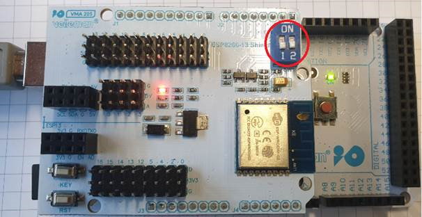
Besides that, the shield has a red led constantly on and both DIP switches are set to ON.
Ok, I saw on the manual that I have to put the DIP switches to OFF. But both or just one? If so which one?
I tried all combinations and the error is the same.
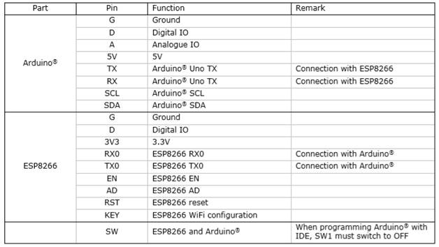
What do the ‘KEY’ and ‘RST’ buttons do ?
Normally it should be possible to upload a sketch to the VMA205 with Arduino IDE 1.8.6 - 1.8.9.
If you want to upload sketch (code) to the ESP Wroom 02 (or ESP2866) module via an Arduino Uno / Mega board, in the Arduino IDE software, the board type in Arduino IDE must be set to Arduino Uno / Mega instead of generic ESP2866 module, (depending of which arduino board you’re using)!
RST button = RESET button Key button is for wifi configuration.
Both dip switches (1/2) must then be set to OFF if you want to upload code to the ESP module.
After uploading, put both DIP switches back ON. Note: for uploading code you don’t need to press the key button!
The dip switch 1/2 is as follows:
These are just the RX and TX (from ESP module) which may or may not be connected to the Arduino
and it is logical that those are OFF if you want to send code (which is not intended for the VMA205) to the arduino.
Thanks for your help. I was able to upload the TCP server with your instructions.
I was trying to use the library included with the following statement :
#include <ESP8266WiFi.h>
which only compiles when I select the “Generic ESP8266 Module”. In that situation I get the timeout when uploading.
Do you know what I have to do to use this library (it comes with the package installed with arduino IDE). I don’t want to use low level AT commands.
I’m trying intensly to somehow get the VMA-205 working without any success.
Tried follow step by step from your manual, but without success. Also tried what it written in this article, also without success. May I ask if you had any chance of a WORKING manual how to use the VMA 205 board in order to use the ESP8266 anyhow? Unfortunatly this product seems NOT to work as described “plug and play” as in the advertisement description. I cannot upload any sketch nor use any serial commands, tried all possible combinations of board settings, baudrate, DIP switches, etc.
I am sending the following AT commands to the board :
  Serial.println("AT+CWMODE_DEF=1");   //Set Wi-Fi mode to 1(Station mode)
  OK_config();
  Serial.println("AT+CWJAP_DEF=\"<my ssid\",\"<my wifi password>\"");//Connect to AP
  OK_config();
  Serial.println("AT+CIPSTA=\"192.168.1.230\",\"255.255.255.0\",\"\"192.168.1.254"); // set the IP address
  OK_config();
  Serial.println("AT+CIPSERVER=1");    //Set TCP Server
I suspect the board is not connecting to my Wifi AP, because of security settings. What should I set up on the AP security wise, in order for the board to connect to it? My AP is doing WPA2 AES with a preshared key.
Hello,
I am now using AT commands to operate the wifi module in the shield. I am also testing a program with the tcp dump program indicated in the manual.
Now I need to know how can I use the digital and analog pins on the shield that connect to the arduino.
The arduino has a row of connectors for the digital inputs and another row for the analog inputs.
The shield has three rows for each. One row with 5 or 3.3V, one with Ground and another one for the input. Do I have to connect the 5V and 3.3V and GND pins to read analog and digital inputs ?