As per the title above, I am having issues with my K8200 printer and I was wondering if anyone here could assist me. I can’t control the printers axes with Repetier, but the axes home correctly when I send the homing commands. In Repetier the bed and extruder thermistors are returning temperatures of around 2 or 3 degC.
I can successfully connect to the printer, but when I try to move the axes I get the following error:
“Printer stopped due errors. Fix these errors and use M999 to restart. (Temperature is reset. Set before restarting)”
The axes do not move when I send manual or G-Code commands. However, I do not think that there is an issue with the drivers as the axes home correctly when I send the homing commands in Repetier. Upon investigation, I have seen it mentioned that the above error and behaviour is associated with unrealistic reported temperatures; when the temperature reported in Repetier returns a value below 5degC the printer is stopped. Both thermistors in my printer are returning temperatures below 5degC in Repetier.
I understand that such low temperature indicate an open circuit, but I am getting suitable resistance (~100 kohm) when I measure the resistance of the thermistors at the THERM1 and THERM2 pins. When I disconnect the thermistors the temperature readings in Repetier do no change. The thermistors are correctly functioning and connected to the PCB, but the printer appears to think that they not.
Also, when I have the printer powered on for a short period of time, the ATMEGA controller on the PCB gets very hot to the touch. I believe that this is indicating a short-circuit and over-current somewhere on the PCB.
In order to help with problem-solving, I found a schematic of the PCB and a list of the components on this forum. A simple continuity check didn’t reveal any issues, but both THERM1 and THERM2 are connected to a 4.7 kohm resistor and 10 uF capacitor also. I haven’t been able to check the capacitors yet, but the THERM8 resistor has a resistance of 4.01 kohm and the THERM7 resistor has a resistance of only 7 ohm. I think that this is definitely a source of the issues with the PCB.
Do you think that these faulty/shorted resistors are the source of my issues? If I replace these components, should it fix the PCB?
Hi, sounds like you have done some serious looking into this.
As you have just joined, am I correct in assumiming this is a new build?
If so, did you use a version of arduino to flash the firmware that was higher that 1.0.6?
1.0.6 is the highest known working version.
When first powered up the axis will only home, then they will respond to normal commands. As the controler doesn’t know where anything is it refuses to move any axis untill it knows their postion.
See how you get on with that & post back.
I had a look through the forums before I posted to see if my problems had been solved before.
I have had the printer up and running for a while now without problem. The issues are only a recent occurance. I left the printer powered on, but not printing. When I went to use it again, I was getting the thermistor issues and I couldn’t control the printer manually. I don’t think there should be an issue with the firmware as it was working correctly and it reports the firmware version when I connect with Repetier.
The resistances I measured also indicate that it is a hardware, not software, problem.
Hi, the 7 ohms measuers way to low, but if it is a wrong component it must have been there from manufacture.
Follows random thoughts:
I sometimes get the error M999 and close repieter, reopen and connect that curest the problem.
Even if the 4.7k resistor is incorrect, it would need to be combined with the thermister in order to draw any current.
If you disconnect both thermisters does the arduino still get hot, is there a difference in the 5v rail with the thermisters connected?
The ribon cable is a known fail, measures good in testing but has broken strands that are not good under load. But there is no load on the thermisters to speak of so that shouldn’t be a problem.
[quote=“Barnabybear”]Hi, the 7 ohms measuers way to low, but if it is a wrong component it must have been there from manufacture.
Follows random thoughts:
I sometimes get the error M999 and close repieter, reopen and connect that curest the problem.
Even if the 4.7k resistor is incorrect, it would need to be combined with the thermister in order to draw any current.
If you disconnect both thermisters does the arduino still get hot, is there a difference in the 5v rail with the thermisters connected?
The ribon cable is a known fail, measures good in testing but has broken strands that are not good under load. But there is no load on the thermisters to speak of so that shouldn’t be a problem.[/quote]
I will try what you suggested. The 7 ohm I measured definitely seemed wrong, but I re-measured the resistance multiple times; maybe I just had issues making contact with the surface mounted resistor?
If the PCB continues to heat up when the thermistors aren’t connected, do you think there would have to be an issue with the ATMega controller itself? That is assuming that the capacitors are okay of course.
[quote=“Dalton”][quote=“Barnabybear”]Hi, the 7 ohms measuers way to low, but if it is a wrong component it must have been there from manufacture.
Follows random thoughts:
I sometimes get the error M999 and close repieter, reopen and connect that curest the problem.
Even if the 4.7k resistor is incorrect, it would need to be combined with the thermister in order to draw any current.
If you disconnect both thermisters does the arduino still get hot, is there a difference in the 5v rail with the thermisters connected?
The ribon cable is a known fail, measures good in testing but has broken strands that are not good under load. But there is no load on the thermisters to speak of so that shouldn’t be a problem.[/quote]
I will try what you suggested. The 7 ohm I measured definitely seemed wrong, but I re-measured the resistance multiple times; maybe I just had issues making contact with the surface mounted resistor?
If the PCB continues to heat up when the thermistors aren’t connected, do you think there would have to be an issue with the ATMega controller itself? That is assuming that the capacitors are okay of course.
I will investigate things again tomorrow.
Thanks.[/quote]
If you measure the resistances the Board power must be off and usb disconnected.
Also disconnect the Thermistors.
Otherwise you will get false resistance readings.
[quote=“Barnabybear”]Hi, the 7 ohms measuers way to low, but if it is a wrong component it must have been there from manufacture.
Follows random thoughts:
I sometimes get the error M999 and close repieter, reopen and connect that curest the problem.
Even if the 4.7k resistor is incorrect, it would need to be combined with the thermister in order to draw any current.
If you disconnect both thermisters does the arduino still get hot, is there a difference in the 5v rail with the thermisters connected?
The ribon cable is a known fail, measures good in testing but has broken strands that are not good under load. But there is no load on the thermisters to speak of so that shouldn’t be a problem.[/quote]
I still have issues with heating when both thermistors are disconnected; the heating occurs when everything is disconnected including the stepper drivers. There is no difference between the 5 V measuring point when I connect the thermistors.
[quote=“ichbinsnur”]
If you measure the resistances the Board power must be off and usb disconnected.
Also disconnect the Thermistors.
Otherwise you will get false resistance readings.
cheers,
Christian[/quote]
I have been measuring the resistances with everything disconnected.
Upon further inspection, resistors R28, R29, R30, and R31 are all reading resistances of ~ 80 ohm. This is much lower than the 100 kohm resistance the spec sheet I have says they should read. Resistor R7 is now also reading a low resistance (~700 ohm) now after I connected the power supply to carry out some further troubleshooting.
While the ATMega controller is heating up when I connect the power supply, the voltage regulator (MC7805ABD2TG) appears to be getting hotter more quickly. Is this normal? My power supply is supplying the correct 15 V.
[quote=“ichbinsnur”]Sounds there is a short circuit somewhere on the board.
The 5v regulator normally doesn’t get hot.
Remove all stepper driver boards, let it cool down and try again.
Does it still heat up?
If so, maybe one of the driver boards is faulty.
cheers,
Christian[/quote]
The heating still occurs when the stepper drivers are disconnected.
Could the low resistance values I’ve measured for R7/8/28/29/30/31 be a source of the current heating? If I have the stepper drivers and thermistors disconnected could these resistors still be causing issues as there is no load? If I just resolder some resistors in place of these ones, could it fix my issues?
I’m not sure how to check for any issues with the capacitors on the board.
The heating still occurs when the stepper drivers are disconnected.
Could the low resistance values I’ve measured for R7/8/28/29/30/31 be a source of the current heating? If I have the stepper drivers and thermistors disconnected could these resistors still be causing issues as there is no load? If I just resolder some resistors in place of these ones, could it fix my issues?
I’m not sure how to check for any issues with the capacitors on the board.[/quote]
Just to make sure, you removed the driver boards from the main PCB, not only disconnected the motors?
The heating still occurs when the stepper drivers are disconnected.
Could the low resistance values I’ve measured for R7/8/28/29/30/31 be a source of the current heating? If I have the stepper drivers and thermistors disconnected could these resistors still be causing issues as there is no load? If I just resolder some resistors in place of these ones, could it fix my issues?
I’m not sure how to check for any issues with the capacitors on the board.[/quote]
Just to make sure, you removed the driver boards from the main PCB, not only disconnected the motors?[/quote]
Yes. I removed the driver boards and disconnected the steppers from the main PCB.
The heating still occurs when the stepper drivers are disconnected.
Could the low resistance values I’ve measured for R7/8/28/29/30/31 be a source of the current heating? If I have the stepper drivers and thermistors disconnected could these resistors still be causing issues as there is no load? If I just resolder some resistors in place of these ones, could it fix my issues?
I’m not sure how to check for any issues with the capacitors on the board.[/quote]
Just to make sure, you removed the driver boards from the main PCB, not only disconnected the motors?[/quote]
Yes. I removed the driver boards and disconnected the steppers from the main PCB.[/quote]
Does the Atmega chip still heat with the drivers pulled?
If not, it can be there is a faulty driver board.
I would then suggest to remount them one at a time and see if you can get the printer to respond.
Does the Atmega chip still heat with the drivers pulled?
If not, it can be there is a faulty driver board.
I would then suggest to remount them one at a time and see if you can get the printer to respond.[/quote]
Yes. The AtMega chip and 5V regulator still heat up when the drivers are pulled. I don’t think there are any issues with the motor drivers as the axes still home correctly.
As there are 6 resistors on the main PCB which are reading incorrect/significantly lowered values (it is like they are somewhat/somehow shorted), I’m assuming that they must be part of the problem. Unless there are other components which are concurrently damaged, it is my guess that replacing the resistors would solve my issues.
Does the Atmega chip still heat with the drivers pulled?
If not, it can be there is a faulty driver board.
I would then suggest to remount them one at a time and see if you can get the printer to respond.[/quote]
Yes. The AtMega chip and 5V regulator still heat up when the drivers are pulled. I don’t think there are any issues with the motor drivers as the axes still home correctly.
As there are 6 resistors on the main PCB which are reading incorrect/significantly lowered values (it is like they are somewhat/somehow shorted), I’m assuming that they must be part of the problem. Unless there are other components which are concurrently damaged, it is my guess that replacing the resistors would solve my issues.[/quote]
I don’t think you have 6 faulty resistors all of the sudden.
There must be a different problem.
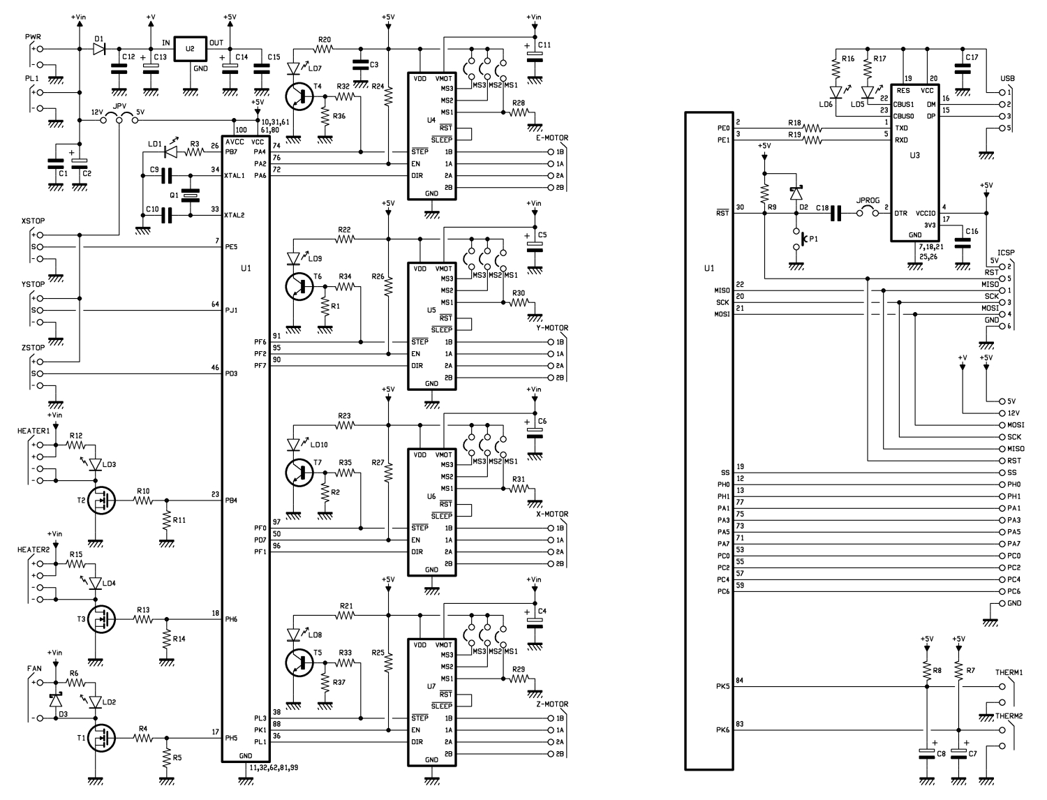
Perhaps it helps to have a look at the controller schematics :
Does the regulator put out 5V or is there significant over or undervoltage?
[quote=“ichbinsnur”][quote=“Dalton”]Yes. The AtMega chip and 5V regulator still heat up when the drivers are pulled. I don’t think there are any issues with the motor drivers as the axes still home correctly.
As there are 6 resistors on the main PCB which are reading incorrect/significantly lowered values (it is like they are somewhat/somehow shorted), I’m assuming that they must be part of the problem. Unless there are other components which are concurrently damaged, it is my guess that replacing the resistors would solve my issues.[/quote]
I don’t think you have 6 faulty resistors all of the sudden.
There must be a different problem.
Perhaps it helps to have a look at the controller schematics :
Does the regulator put out 5V or is there significant over or undervoltage?[/quote]
The regulator puts out the correct 5 V and the resistors are definitely reading incorrect values; I have checked them multiple times. Every other resistor on the board is reading the correct value.
I have been using that schematic to help with my troubleshooting; it is very helpful. Each of the damaged resistors for the stepper drivers (R28, R29, R30, and R31) serve the same purpose for each of the stepper drivers, and the two damaged resistors for the thermistors (R7 and R8) serve the same purpose also. I think it would be too much of a coincidence for only these resistors to be reading incorrect values due to an error on my part.
I know that it seems unbelievable that so many resistors could be damaged, but it is the only obvious fault I have found with the board. The end stops and fan are working correctly, and I believe that the steppers would also be working correctly if I could circumvent the safety for low temperatures being read at the thermistors.
[quote=“ichbinsnur”]Quite strange.
I can’t imagine a scenario which would damage all tohe resistors at once.
At least not without damaging the Atmega as well.[/quote]
As I can still control the printer using the PCB, would it indicate that the AtMega controller is still in good health? Could there be a fault with another component which caused the problems with the resistances I found?
Is there a way to troubleshoot issues with any of the components?
Thanks for all your help too, actually. I hope that I haven’t come off short with you.
Since the resistors are still in the circuit you may not get a correct reading because of the other components.
The only way to get a true reading is remove each one or at least one leg from the board.
Hi, R7 & R8 are connected to 5V at one end & a capacitor at the other depending on the length of time the board has been powerd down & which way round you have the test leads you could get some strange results. When you measure resistance you effectively measure the effect that a resistor has on a voltage provided by the test equipment. If another voltage is pressent it can have an effect. Also capacitors can charge using the voltage from the test equipmnet affecting the result.
You can check for any voltage at each end of the resistor measuring to ground (0v) before testing & hold the test leads in place for some time to let any capacitors charge to the test voltage then you will get a ‘more’ correct reading.
As stated by Wrong Way disconnecting one end of a component is the only way to get a accurate result. Nearly impossable with surface mounted components, and I dont recomend that you attempt that without more testing as that many not be the problem.
Edit: it might be worth powering the board with a direct 5V and seeing if it still gets warm. You can’t use the normal power terminals as by the time the voltage had passed the input diode and the regulator you would only end up with at best 4V. However on the display output terminals there is both 5V and 0V. If you have a set of header pins, it might be worth soldering them in and powering the board that way with drivers removed. You should still get communication with the PC, and as the Atmega and the regulator share cooling via the ground plane it would iliminate heating from the voltage regulator. If all says cool you can replace the drivers one at a time. It should give you a better idea of where the heat is comming from.
Hi, had a quick play this morning. If you find this section in configuration.h
[code]//===========================================================================
//=============================Thermal Settings ============================
//===========================================================================
//
//–NORMAL IS 4.7kohm PULLUP!-- 1kohm pullup can be used on hotend sensor, using correct resistor and table
//
//// Temperature sensor settings:
// -2 is thermocouple with MAX6675 (only for sensor 0)
// -1 is thermocouple with AD595
// 0 is not used
// 1 is 100k thermistor - best choice for EPCOS 100k (4.7k pullup)
// 2 is 200k thermistor - ATC Semitec 204GT-2 (4.7k pullup)
// 3 is mendel-parts thermistor (4.7k pullup)
// 4 is 10k thermistor !! do not use it for a hotend. It gives bad resolution at high temp. !!
// 5 is 100K thermistor - ATC Semitec 104GT-2 (Used in ParCan) (4.7k pullup)
// 6 is 100k EPCOS - Not as accurate as table 1 (created using a fluke thermocouple) (4.7k pullup)
// 7 is 100k Honeywell thermistor 135-104LAG-J01 (4.7k pullup)
// 8 is 100k 0603 SMD Vishay NTCS0603E3104FXT (4.7k pullup)
// 9 is 100k GE Sensing AL03006-58.2K-97-G1 (4.7k pullup)
// 10 is 100k RS thermistor 198-961 (4.7k pullup)
//
// 1k ohm pullup tables - This is not normal, you would have to have changed out your 4.7k for 1k
// (but gives greater accuracy and more stable PID)
// 51 is 100k thermistor - EPCOS (1k pullup)
// 52 is 200k thermistor - ATC Semitec 204GT-2 (1k pullup)
// 55 is 100k thermistor - ATC Semitec 104GT-2 (Used in ParCan) (1k pullup)
#define TEMP_SENSOR_0 5 //========NOT THIS LINE EVEN THOUGH IT LOOKS THE SAME======== #define TEMP_SENSOR_1 0 #define TEMP_SENSOR_2 0 #define TEMP_SENSOR_BED 5
// This makes temp sensor 1 a redundant sensor for sensor 0. If the temperatures difference between these sensors is to high the print will be aborted.
//#define TEMP_SENSOR_1_AS_REDUNDANT #define MAX_REDUNDANT_TEMP_SENSOR_DIFF 10
// Actual temperature must be close to target for this long before M109 returns success #define TEMP_RESIDENCY_TIME 10 // (seconds) #define TEMP_HYSTERESIS 3 // (degC) range of +/- temperatures considered “close” to the target one #define TEMP_WINDOW 1 // (degC) Window around target to start the recidency timer x degC early.
// The minimal temperature defines the temperature below which the heater will not be enabled It is used
// to check that the wiring to the thermistor is not broken.
// Otherwise this would lead to the heater being powered on all the time. #define HEATER_0_MINTEMP 5 //========CHANGE THIS VALUE FROM 5 TO 0======== #define HEATER_1_MINTEMP 5 #define HEATER_2_MINTEMP 5 #define BED_MINTEMP 5
[/code]
and change this line ‘#define HEATER_0_MINTEMP 5’ to ‘#define HEATER_0_MINTEMP 0’ reflash the firmware using a version of arduino NOT highter than 1.0.6, it will remove the safety feature that prevents the axis moving if the extruder therimistor is not connected. [color=#BF0000]Please do not leave the printer powered up unatteneded or request any heating to the extruder with this feature disabled, it is to test the steppers only.[/color]
Note there is a line abave that looks very simalar.
Whilst it will not cure the thermister problem, it will verify that the axis are working. I’m not sure that the heat and resistance values are a distraction from a broken wire or bad connetor.