Allright, thanks, don’t abandon this thread, as I will countinue working on my K8200 tomorrow, after I finish my midterms in electrical and electronical circuits, I will have a lot of questions. 
Hello everyone again, I am back with my questions.
- What settings should I increase/decrease to get flatter and smotther first layer? I am printing on a mirror. Here are current results.


- What settings should I increase/decrease, to get better top layer? These are current results

- Which settings shoud I increase/decrease, while printing layer on a hole? Cause now first layers above air tend to fall down a little. I am talking about something like this:
youtube.com/watch?v=wQbkjDKtFwI
Thanks
Hi Linas_capas,
looks like you have quite large Z wobble (probably the reason for printing the motor mount …).
First layer quality depends on the right amount of filament (see below) and the right Z home setting. When you test-print only one layer (or stop a print within the first layer) and measure the height with a calliper, does it match your set first layer height?
About the amount of filament, did you calibrate the extrusion multiplier yet?
The top layer of the flat part seems to be in a region where the Z wobble causes the real layer height to be larger than set, which would be a part of the problem with the extrusion being too thin.
Finally, bridging: vast topic. Temperature setting, cooling (fan on, air duct / fan nozzle installed?), speed, acceleration, etc. all influence the results, so there’s no definitive answer. For small holes like the ones present in the motor holder, just cut or file or drill out what’s too much. Or in other words: target the large errors (Z wobble etc.) first, then do the fine tuning.
Cheers,
kuraasu
Kuraasu, thanks for reply. Yes, I have calibrated the extruder for right amounts extruded. And yes, Z wobble is insane, I am waiting for my trapezoid spindels, I will add parallel Z axis. I will check first layer height in a bit
Hello everyone again. I assembled the new Z motor mount, but my motor stopped working. Even when taken out from the mount, the motor does not turn. There is vibration and normal sound coming from coils, but the shaft does not turn. My stepper voltage is set to 0.425 for each driver.
Check the cables, vibrating forth and back is a sign of one coil being disconnected. On the connector (unplugged from the board), both coils should have a resistance near 2 Ω. Pins 1 & 2 is one coil, 3 & 4 the other.
Thanks again kuraasu, You where right. However, my little brother ripped usb connection from the board, is it possible to resolder it again? Cause basicly, its only PCB left and it will not solder to PCB.
Can you post a high-res photo of the part of the board?
I managed to solder 3 legs back to place, only this left:

If you need more photos or better quality ones, let me know
Sorry, but I’m afraid that won’t help. For one thing, the visible solder joint is “cold”, since it does not really connect to the board. But those sideways legs of the socket are only for shielding and mechanical stability anyways. The five small SMD-like pins on the backside of the connector are the ones that matter (actually, four of those five).
How does it look over there?
I think I will take my board to soldering store and get my usb port from the board to a wired cable, so I would have the “extended” cable. Is it possible?
I’m not quite sure what you mean by “extended”, but from Topbox’ post it seems to be possible (depending on what exactly broke when the socket came off) to solder the leads of an USB cable directly to the board.
That is exactly what I meant. Thanks, I will let you know how it ended up for me.
Can anyone point me out the places which wire solder to? I am too afraid to damage my board soldering myself.
This is the picture of Topbox soldering, but I can not clearly see the places where he soldered each wire.
i976.photobucket.com/albums/ae24 … 158f02.jpg
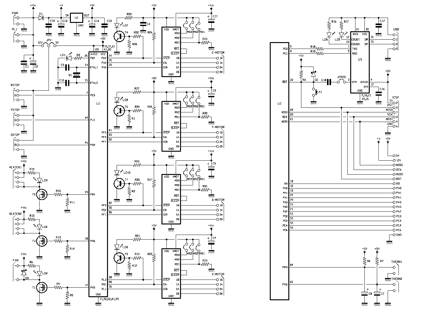
Also, there is schematic of the controller board:
velleman.eu/images/tmp/K8200diagram.jpg
And this is my board. If someone could circle the places which wire I need to solder to, I would be thankfull.
fbcdn-sphotos-h-a.akamaihd.net/ … 70b33b17bc
Hello
here a link with details of what u need
Good luck
Hi Linas_capas,
the points for the data wires (white and green) are visible from both Topbox’ and Tag’s photos, as is the one for the USB5V (red). However, the pad that Tag used for GND (black) seems to be gone on your board, so you need to use a different connection there. The sideways leg of the black power socket is one possibility (if you look closely on Topbox’ photo, you can see the end of the black cable below the red one). You can also use the conductivity test mode of your multimeter if you are unsure, check against the “-” socket of the power input terminal which is GND level for the board.
Cheers,
kuraasu
[size=85](Edit: got Tag’s name wrong, sorry for that)[/size]
kuraasu gives u the best way to do so, and u can do it for all cables.
At the end, dont forget to pass the wire in the screw hole and glue it, just to avoid another drama ![]()
Thanks everyone, my printer is running fine now. 
Now I am deciding, which trapezoidial spindle to make. I live in Lithuania, so ebay shipping usually takes long time, and I checked all local stores, only these two are availabe: TR8x1 or TR10x2. Any advices which to choose?
Nice, I’m happy for u.
Then in the meantime ur waiting the parts for the Z axes modifications, U can improve ur Slicr configurations and printing  and share ur Slicr adjustments
Just do the simple optimisation of Z axis motor mount first of all.
Have fun
Hi Linas_capas,
is it TR8x1 or x1,5?
Cheers,
kuraasu